www.mc-techgroup.com CSS-VC-1.6 | 1.01.03 19
12 SUPPLY CONNECTIONS
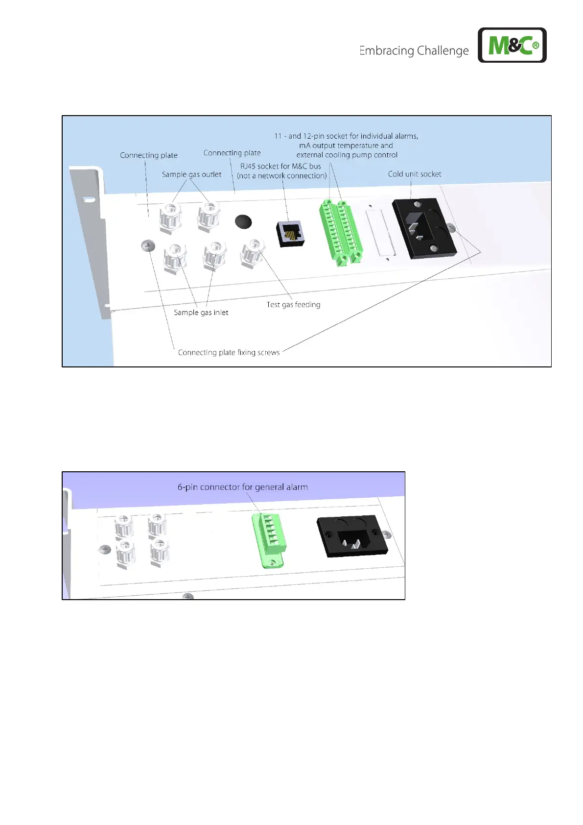
Figure 3 Connections in the connection panel of the CSS-VC..
Depending on the version of the CSS-VC, instead of the 11 and 12-pin connector for single alarms, mA
output cooler temperature and external sample gas pump control, a 6-pin connector may also be present
for group alarm (see Figure 4 ). The sample gas inlet, depending on the version, may also lie directly on
the heat exchangers.
Figure 4 Connection group alarm
In the portable version of the CSS-VC.., the supply connectors shown above are located on the rear
panel of the housing. The RJ45 connector is not present here. With the temperature controller option for
the portable version (Part No. 01G6190), a 7-pin connector (see section 12.4.3) is present at the position
of the RJ45 connector in Figure 3.