www.mc-techgroup.com CSS-VC-1.6 | 1.01.03 21
12.2 LAY THE CONNECTORS ON THE REAR PANEL
If, for example with the 19" mounting, mounting conditions require the connections to be moved up in
the connection panel onto the back of the device, this is quite possible:
• Remove the connection-panel mounting screws (see Figure 3)
• Remove the cover-bracket mounting screws on the rear panel
• Mount the connection plate with 2 mounting screws on the rear panel
• Mount the cover bracket with 2 connection screws on the device cover
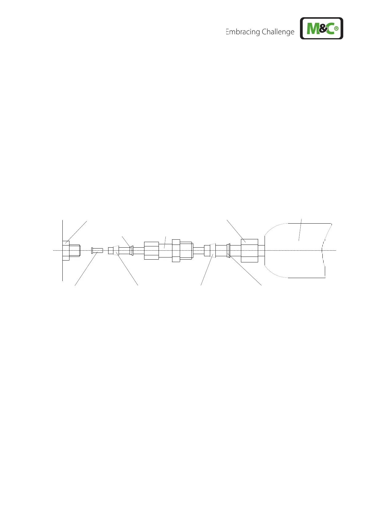
12.3 CONNECTION OF THE HEATED LINE WITH ANTIKINK ADAPTER FOR
PORTABLE VERSION (ART. NO. 01G9060 OR 01G9061)
Sample gas
IN
bulkhead fitting
Figure 5 Connecting heated line DN4/6 with antikink adapter
• Place special adapters according to the above drawing on Teflon tubing;
• Slide the support sleeve slide into the Teflon tubing;
• Draw the Teflon tubing all the way into the bulkhead union 'Sample Gas ON' and hand-tighten
the adapter;
• Tighten the adapter with wrench (SW 14) 1 1/4 turns; here hold the lock nut of the bulkhead
union with a wrench (SW 15);
• Insert the 10 mm pipe of the heating line all the way into the adapter and hand-tighten using the
nut;
• Tighten nut with wrench (SW 19), 1 1/4 turns; here hold the adapter with wrench;
The union is now cut to be gas-tight and can be loosened as often as required.