47
IT
EN
DE
5
MRT 1850 - 2150 - 2540
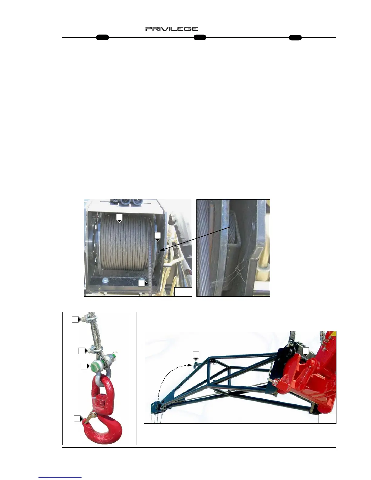
- check the condition of the rope
B (Fig.3) and its winding around drum
A (Fig.3);
- check the correct movement and
rotation of the rope guide pulleys
F1 (Fig.2);
- check the condition of terminal
C (Fig.3);
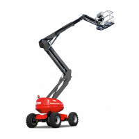
- check to make sure the shackle
connecting the rope and hook is
screwed on properly K (Fig.4) and that
terminals K1 (Fig.4) block the rope.
- check the hook: make sure it is not
deformed, that it turns freely and that
the safety tab is efficient G (Fig.4);
- check the hooking of the arm to the
operating machine J (Fig.5).
From the parking position, it is possible
to unhook the supporting feet and posi-
tion it inside the arm to work without
further impediment J1 (Fig.5).
- Den Zustand des Seils B prüfen
(Abb. 3) und die korrekte Aufwicklung
um die Trommel A prüfen (Abb. 3).
- Die korrekte Seiten- und
Rotationsbewegung der
Seillenkscheibe F1 prüfen (Abb. 2).
- Den Zustand der Kabelschlaufen
C (Abb. 3) prüfen.
- Sicherstellen, dass der
Seilverbindungsschäkel und der
Kranhaken gut eingeschraubt sind
K (Abb. 4) und dass die Klemmen
K1 (Abb. 4) das Seil blockieren.
- Den Zustand des Kranhakens prüfen:
Er darf nicht deformiert sein, muss sich
frei drehen können und der
Sicherheitskeil G muss effizient sein
(Abb. 4).
- Sicherstellen, dass die Winde an der
Arbeitsmaschine J eingerastet ist
(Abb. 5).
Aus der Abstellposition die Winde kann
man den Abstellfuß ausklinken und ihn
innerhalb des Auslegers anordnen, ohne
noch mehr Platz in Anspruch zu
nehmen. J1 (Abb. 5)
- controllare lo stato della fune B (Fig.3)
e il corretto avvolgimento sul tamburo
A (Fig.3);
- controllare il corretto movimento
rotazione delle puleggie di
guida fune F1 (Fig.2);
- controllare lo stato del capocorda
C (Fig.3);
- controllare che il grillo di collegamento
fune e gancio sia ben avvitato K (Fig.4)
e che i morsetti K1 (Fig.4) blocchino la fune.
- verificare lo stato del gancio: che non
sia deformato, che ruoti liberamente e
che la linguetta di sicurezza sia
efficente G (Fig.4);
- controllare l’aggancio del braccetto alla
macchina operatrice J (Fig.5).
Dalla posizione di parcheggio è possibile
sganciare il piede di appoggio e
posizionarlo all’interno del braccetto per
operare senza ulteriori ingombri J1 (Fig.5).
3
A
B
4
5
G
J1
J
C
K
K1
K1