34
IT
EN
DE
5
MRT 1850 - 2150 - 2540
USING THE WINCH ON THE
BOOM
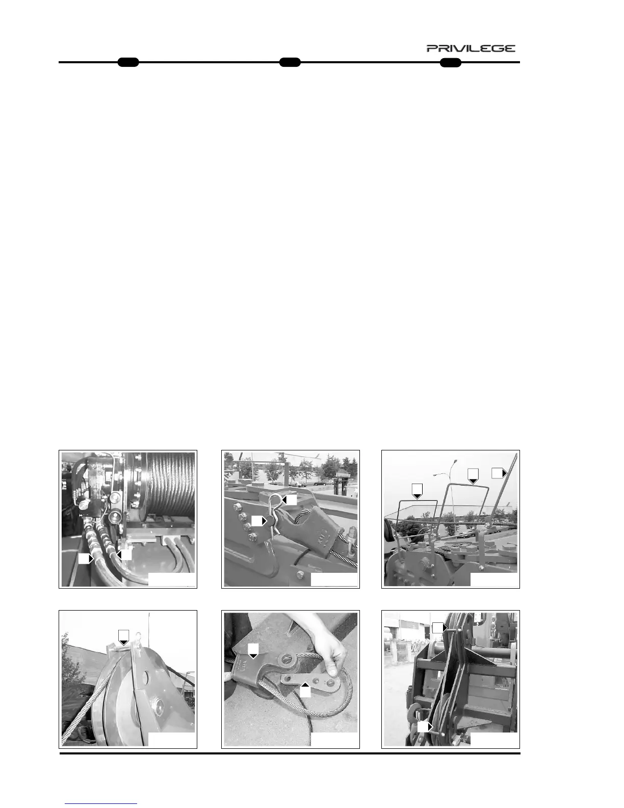
ACTIVATING THE WINCH
- Connect the hydraulic fittings to the
winch (Fig. 1 - Ref. A).
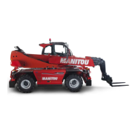
- Remove the cotter pin (Fig. 2 - Ref. B)
and extract the pin from clevis on the
outside boom (Fig. 2 - Ref. C).
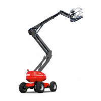
- Lower the rope to let it pass through
the three rope guides (Fig. 3 - Ref. D).
- Insert the rope in the pulley, removing
the pin (Fig. 4 - Ref. E).
- Free the rope from the cable clamp
(Fig. 5 - Ref. F) after removing the
safety clamp.
- Insert the rope in the rope guide pulley
(Fig. 6 - Ref. G).
WINDENGEBRAUCH AM
AUSLEGER
WINDENAKTIVIERUNG
- Die hydraulischen Anschlußstücke mit
der Winde verbinden (Abb. 1 - Buchst.
A).
- Den Splint (Abb. 2 - Buchst. B) entfer-
nen und den Zapfen aus dem
Ruhebügel am äußeren Ausleger (Abb.
2 - Buchst. C) herausziehen.
- Das Seil absenken, damit der
Durchgang durch die drei
Seilführungen (Abb. 3 - Buchst. D)
möglich ist.
- Das Seil in die Riemenscheibe einfüh-
ren, indem man den Zapfen (Abb. 4 -
Buchst. E) entfernt.
- Das Seil vom Seilanschlag (Abb. 5 -
Bez. F) freigeben, indem man die
Seilklemme entfernt
- Das Seil in die Seilführungs-
Riemenscheiben (Abb. 6 - Buchst. G)
einführen.
UTILIZZO DELL’ARGANO SUL
BRACCIO
ATTIVAZIONE ARGANO
- Collegare i raccordi idraulici all’argano
(Fig. 1 - Rif. A).
- Togliere la coppiglia (Fig. 2 - Rif. B) e
sfilare il perno dalla staffa di riposo sul
braccio esterno (Fig. 2 - Rif. C).
- Comandare la discesa della fune per
permettere il passaggio attraverso i tre
guida fune (Fig. 3 - Rif. D).
- Inserire la fune nella puleggia toglien-
do il perno (Fig. 4 - Rif. E).
- Liberare la fune dal ferma cavo (Fig. 5
- Rif. F) togliendo il morsetto di sicu-
rezza.
- Inserire la fune nelle pulegge guida
fune (Fig. 6 - Rif. G).
FIG. 2 FIG. 3
FIG. 5 FIG. 6FIG. 4
FIG. 1
C
B
D
D
D
E
F
F
G
G
A
A