5-6
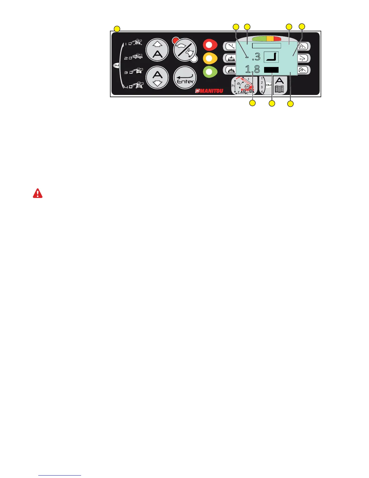
Main Working Data Reading on the display.
8 - WEIGHT OF LIFTED LOAD,,
Symbol: ACT (reading in “Tonnes”, with a decimal point).
9 - MAXIMUM ADMITTED LOAD: In machine present configuration.
Graphic symbol:
MAX (Reading in “Tonnes”, with a decimal point).
10 - WORKING RADIUS: distance from the centre of turret rotation to applied load.
Graphic symbol :
r (Reading in “Metres”, with a decimal point).
11 - OPERATING CONFIGURATION.
The first figure concerns the operating mode
(OM) while the second figure concerns the attachment used (A - to obtain correct letter-accessory references, consult the manual
(chap. 5) or the diagram book e.g. : A= forks, C= Winch 3T....).
In case of Imperial Measure System, the weight will be defined in “Pounds/1000” and the geometric data in “Feet”.
12 - BOOM LENGTH.
Graphic Symbol :
l (Reading in “Metres”, with a decimal point).
13 - BOOM ANGLE.
Graphic Symbol :
a (Reading in “Degrees” with a decimal point).
14 - HEIGHT FROM GROUND.
Graphic Symbol :
h (Reading in “Metres”, with a decimal point).
5.8
5.9
4.3
34
1.8
- .3
2A
12
10
8
9
11
13
14
C