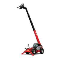
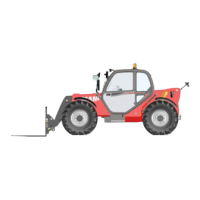
Do you have a question about the Manitou MT8044XT and is the answer not in the manual?
Symbol indicating potential safety hazards and the need for alertness.
Details maximum lift capacity, height, and reach for various models.
Provides overall length, width, height, ground clearance, and wheelbase.
Lists gauges, lights, steering, braking, and electrical system details.
Lists fluid capacities for cooling, fuel, transmission, axles, and hydraulic systems.
Details engine specifications and hydraulic system components.
Inspections and information exchange for machine delivery.
Definitions for hazard levels, shutdown procedures, and general safety reminders.
Reminders for safe machine operation, including load handling and slopes.
Safety for PWP systems, guards, servicing, and fall protection compliance.
Location of controls, indicators, and general warnings in the operator's area.
Details ignition, instruments, gauges, and indicator lamps on the dash.
Operation of various switches, override, and exhaust filter controls.
Operation of heater, travel lever, throttle, brake pedals, and seat belt.
Operation of joystick configurations, auxiliary hydraulics, and speed controls.
Details on hydraulic valves and function indicators like frame level.
Engine break-in, general operation, pre-start inspection, and starting/stopping the engine.
Operation of engine protection, coolant temp, exhaust filter, and cleaning modes.
Parking brake, attachment handling, self-leveling, load capacity, and suspended loads.
PWP installation, elevating personnel, road travel, and jobsite transport.
General notes, lubricant chart, and specific fluid types.
Instructions for greasing and lists of fitting locations by area.
Lists filter types and part numbers.
Notes on service routines, precautions, and dealer services.
Steps for storing the machine, including before, during, and after storage.
Purpose of decal info, caution, new decal application, and kits.
Lists of decal locations for frame, boom, operator station, and PWP units.
Chart detailing service procedures and intervals.
Section for recording performed maintenance.
List of Suspect Parameter Numbers and their definitions.
List of Failure Mode Identifiers and their definitions.
Hydraulic diagrams for two-joystick configurations.
Hydraulic diagrams for tri-function joystick configurations.
Electrical diagrams for machines with and without radio remote control.
Load charts for the MT6642XT model.
Load charts for the MT8044XT model.
Load charts for the MT10044XT model.
Load charts for the MT12042XT model.
Load charts for the MT10055XT model.
Covers service inclusions, exclusions, and warranty disclaimers.


 Loading...