EasyManua.ls Logo

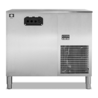
Manitowoc Multiplex 44MR04

Manitowoc Multiplex 44MR04
52 pages
To Next Page IconTo Next Page
Loading...
Part Number 020002365 08/25/2015
Post Mix Soda and Super-Chilâ„¢
Refrigeration Unit with Electronic Control
Installation, Operation and Maintenance Manual
This manual is updated as new information and models are released. Visit our website fo rthe latest manual.
www.manitowocbeverage.com/us

Table of Contents

Questions and Answers:

Manitowoc Multiplex 44MR04 Specifications

General IconGeneral
BrandManitowoc
ModelMultiplex 44MR04
CategoryChiller
LanguageEnglish

Summary

Safety Notices and Pre-Installation Guidance

Essential Pre-Installation Warnings

Critical safety information and warnings to review before proceeding with installation.

Section 2: Installation - General and Location Requirements

Dimensions and Clearance Specifications

Provides specific physical dimensions and clearance requirements for all models.

Section 2: Installation - Condenser and Safety Practices

Safe Installation Dos and Donts Guidelines

Critical safety guidelines and best practices for installation.

Section 2: Installation - Location and System Requirements

Section 2: Installation - Installer and Electrical Setup

Electrical Requirements and Specifications

Details electrical specifications, circuit ampacity, and breaker requirements.

Section 2: Installation - Electrical Safety and Grounding

Mandatory Grounding Instructions

Mandatory grounding procedures to prevent electric shock.

Section 2: Installation - Plumbing and Water Supply

Potable Water Connection Requirements

Specifies water pressure, connections, and code compliance for potable water.

Section 2: Installation - Water Circuit Diagrams (Models 42, 44, SC1000)

Pressurized Water Circuit Schematic

Schematic of the pressurized water circuit for specific models.

Section 2: Installation - Water Circuit Diagrams (Models 50, SC2000)

Pressurized Water Circuit Schematic for 50 SC2000

Schematic of the pressurized water circuit for models 50 and SC2000.

Section 2: Installation - CO2 and Compressed Air Diagrams

CO2 Gas and Compressed Air Circuit Schematic

Diagram illustrating the CO2 gas and compressed air lines and components.

Section 2: Installation - Unit Unpacking and Setup

Unpacking and Inspection Procedures

Steps for inspecting the unit and its components upon delivery.

Section 2: Installation - Unit Placement and Electrical Connections

Refrigeration Unit Positioning and Leveling

Guidelines for placing the refrigeration unit and its stand.

Electrical Connection Procedure

Procedure for making electrical connections to the unit.

Section 2: Installation - Conduit and John Guest Fittings

Proper Usage of John Guest Fittings

Step-by-step guide on using compression type tube connectors.

Section 2: Installation - Carbonated Water Line Diagrams and Testing

Carbonated Water Supply Line Diagram Details

Detailed diagram for carbonated water supply lines to towers.

Section 2: Installation - Insulated Conduit and Line Connections

Connecting Insulated Conduit at the Unit

Procedure for connecting conduit lines to the refrigeration unit.

Connecting Insulated Beverage Lines

Steps for connecting insulated beverage conduit at the unit.

Section 2: Installation - Refrigerant Line Connections and Testing

Testing the CO2 Circuit for Leaks

Procedure for testing the CO2 circuit for leaks using pressure.

Testing the Syrup Circuit for Leaks

Procedure for testing syrup circuits for leaks using CO2 gas.

Section 2: Installation - Ice Bank Formation and Final Checks

Building the Ice Bank Procedure

Steps to fill the water bath and build the ice bank.

Section 3: Operation Overview

Section 3: Operation - System Functionality and Start-Up

Equipment Start-Up Procedure

Steps for initial setup and starting the equipment.

Placing the Syrup System into Operation

Procedure for putting the syrup delivery system into operation.

Section 3: Operation - Control Sequence and Programming

Error Codes and System Display Indicators

List of error codes and how they are displayed.

Section 3: Operation - ERC Programming Flowcharts

Section 3: Operation - ERC Energy Saving Mode Flowchart

ERC Programming Flowchart - Mode 5 Operation

Detailed flowchart for enabling and operating Energy Saving Mode.

Section 4: Maintenance Overview and Schedule

Refrigeration Unit Regular Maintenance

Regular tasks for cleaning condensers, water baths, and motors.

Section 4: Maintenance - Beverage System Sanitization

Bag-In-Box System Sanitation Procedure

Step-by-step procedure for sanitizing one syrup circuit at a time.

Section 4: Maintenance - Preventer Checks and Relocation Precautions

Annual Back-Flow Preventer Maintenance

Procedure for checking the back-flow preventer annually.

Section 5: Troubleshooting Common Issues

Troubleshooting Problem Checklist

Checklist of common problems and their potential causes and solutions.

Section 5: Troubleshooting - Error Codes and Displays

Summary of Error Codes and Causes

Table listing error codes, their descriptions, and common causes.

Section 5: Troubleshooting - Flowcharts for Pressure and Level Errors

Diagnostic Flowchart for Errors E1, E2, E3

Diagnostic flowchart for errors E1, E2, and E3 related to pressure and water level.

Section 5: Troubleshooting - Flowcharts for Temperature and Pressure Errors

Diagnostic Flowchart for Errors E4, E5, E6

Diagnostic flowchart for errors E4, E5, and E6 related to temperature and pressure.

Section 5: Troubleshooting - Flowcharts for Ice Bank and Run Time Errors

Diagnostic Flowchart for Errors E7, E8, E9

Diagnostic flowchart for errors E7, E8, and E9 related to ice bank and run times.

Related product manuals