EasyManua.ls Logo

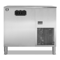
Manitowoc Multiplex SC2000A

Manitowoc Multiplex SC2000A
52 pages
To Next Page IconTo Next Page
Loading...
Part Number 020002365 08/25/2015
Post Mix Soda and Super-Chilâ„¢
Refrigeration Unit with Electronic Control
Installation, Operation and Maintenance Manual
This manual is updated as new information and models are released. Visit our website fo rthe latest manual.
www.manitowocbeverage.com/us

Table of Contents

Questions and Answers:

Manitowoc Multiplex SC2000A Specifications

General IconGeneral
BrandManitowoc
ModelMultiplex SC2000A
CategoryChiller
LanguageEnglish

Summary

Section 2 Installation

Dimensions and Clearances - All Models

Specifies required space around the unit for airflow and access.

Safe Installation Dos and Donts

Provides critical safety guidelines and mandatory practices for installation.

Electrical

Covers general electrical requirements and safety precautions.

Grounding Instructions

Details essential grounding procedures to prevent electric shock.

PlumbingWater Supply

Specifies potable water connection requirements and pressure limits.

Plumbing Circuit Diagrams - Models 42, 44 and SC1000

Illustrates the water circuit for specific models.

Pre-mix Plumbing - Eight Valve Towers with Connection at Center Island

Diagrams syrup line connections for various tower configurations.

Carbonated Water Plumbing - Eight Valve Towers with Connection at Unit

Diagrams carbonated water line connections for tower setups.

Plumbing Circuit Diagrams - Models 50 and SC2000

Illustrates the water circuit for different models.

CO Gas and Compressed Air Circuit Diagram

Shows the gas and air supply lines and components.

Electrical Connections

Steps for safely connecting the unit's power supply.

Carbonated Water Supply Line Diagram

Diagrams for connecting carbonated water lines to towers.

Connecting the Pre-charged Refrigeration Lines

Steps for making secure connections of refrigerant lines.

Testing

Procedures for testing CO2 and syrup circuits for leaks.

Preparing Ice Bank

Instructions for filling the water bath and building the ice bank.

Section 3 Operation

Start-Up

Initial procedures for powering on and preparing the equipment.

Section 4 Maintenance

Cleaning and Sanitizing the Dispensing Valves and Product Lines

Procedures for cleaning dispensing components.

Section 5 Troubleshooting

Checklist

Guide to diagnose common operational problems and their solutions.

E1, E2, & E3 Flowchart

Diagnostic flowchart for specific error codes related to pressure and water level.

E4, E5, & E6 Flowchart

Diagnostic flowchart for errors related to temperature and pressure.

E7, E8, & E9 Flowchart

Diagnostic flowchart for errors related to ice bank, run time, and pumps.

Related product manuals