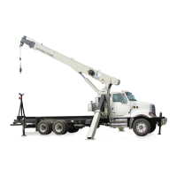
SET-UP OPERATOR MANUAL NBT50
4-18 Published 03-23-2018 Control # 243-14
8. Using Counterweight Switch Panel (Figure 4-13) located
on either side of turntable, lower the Counterweight
Removal Cylinders by doing the following:
NOTE: The Counterweight Switch Panels will only function
if the Crane Function Power Switch is turned off, an
armrest is in the up position, or there is no one
sitting in the crane cab operator’s seat. A green
LED (6, Figure 4-13) on the left side of the
Counterweight Switch Panel will illuminate to
indicate the panel is operational.
If a Counterweight Removal Cylinder Raise or
Lower Button (4, 5, Figure 4-13) is pressed without
first pressing and holding a Power Button (1,
Figure 4-13), a red LED above that button will
flash.
a. Press and hold a Power Button.
FIGURE 4-12
1 Cast Section - Top (3000 lb)
2 Cast Section - Bottom (3000 lb)
3 Removal Cylinders
4 Superstructure Attachment Pin
5 Cylinder Attachment Pin
6 Section Attachment Pin
7 Carrier Deck Attachment Pin
8 Switch Panel
1
2
3
4
5
6
7
8
7869-1
 Loading...


