Do you have a question about the Manitowoc QD0603W and is the answer not in the manual?
Details types of safety notices: Warning (injury), Caution (damage).
Details types of procedural notices: Important (efficiency).
Lists models covered and dimensions of ice cube sizes.
Refers to separate manual for complete installation guidelines.
Provides dimensions for Q320, Q370, and Q420 ice machines.
Covers remote wiring, water supply, drain requirements, and condenser installation.
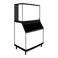
Identifies key components of the ice machine.
Provides procedures for cleaning and sanitizing the ice machine interior.
Discusses water treatment systems and filter replacement procedures.
Details procedures for removing the machine from service or winterizing it.
Explains operational sequences for self-contained and remote models.
Contains electrical wiring diagrams for various models.
Details specifications and diagnostic procedures for electrical components.
Describes the refrigeration sequence for self-contained and remote models.
Guides on analyzing refrigeration system malfunctions.
Provides procedures for refrigerant recovery, evacuation, and recharging.
Lists models covered and dimensions of ice cube sizes.
Alerts to potential personal injury from misuse or alteration of equipment.
Shows where to find model and serial number decals on the machine.
Outlines warranty coverage for parts, labor, and exclusions.
Specifies requirements for authorized warranty service.
Refers to a separate manual for complete installation guidelines.
Provides dimensions for Q320, Q370, and Q420 ice machines.
Details dimensions for Q200 through Q1000 series ice machines.
Details dimensions for Q1300, Q1600, and Q1800 ice machines.
Continues dimensions for Q1300, Q1600, and Q1800 ice machines.
Provides dimensions for S170, S400, S570, S320, and S420 ice storage bins.
Details dimensions for the S970 ice storage bin.
Provides dimensions for JC0495/JC0895/JC1095/JC1395 and JC1895 remote condensers.
Specifies criteria for selecting the ice machine location.
Explains requirements for stacking two ice machines.
Provides BTU/hr heat rejection data for various ice machine models.
Provides instructions for leveling the ice storage bin.
Details the installation of the air-cooled baffle.
Covers general electrical service, voltage, and fuse/breaker specifications.
Lists electrical specifications for Q320, Q370, Q420 ice machines.
Lists electrical specifications for Q200 through Q1000 ice machines.
Provides wiring diagrams for self-contained ice machines.
Provides wiring diagrams for remote ice machines.
Outlines requirements for water supply and drain connections.
Discusses water supply and drain line sizing for water-cooled models.
Details water supply and drain line sizing and connections.
Covers installation guidelines for remote condensers and line sets.
Provides guidelines for routing refrigerant lines for remote condensers.
Explains how to calculate safe line set lengths and distances.
Details procedures for adjusting line set lengths.
Provides instructions for connecting refrigerant line sets.
Instructions for opening the receiver service valve.
Discusses warranty and usage guidelines for non-Manitowoc condensers.
Specifies requirements for head pressure control valves.
Explains fan motor operation, internal volume, and condenser ∆T.
Details refrigerant charge and quick connect fittings for remote machines.
Provides a chart for sizing non-Manitowoc multi-circuit condensers.
A checklist for verifying proper installation steps.
Specific checks required for remote ice machine installations.
Identifies key components of the ice machine with a diagram.
Outlines general operational checks and water level checks.
Details how to check and adjust ice thickness.
Explains the adjustment for harvest sequence water purge.
Provides instructions for cleaning air-cooled condensers.
Discusses cleaning water-cooled condensers and regulating valves.
Provides procedures for cleaning and sanitizing the ice machine interior.
Explains Manitowoc's automatic cleaning and sanitizing technology.
Describes AlphaSan's role in keeping plastic surfaces clean.
Step-by-step guide for cleaning the ice machine.
Step-by-step guide for sanitizing the ice machine.
Details the operation and functions of the AuCS accessory.
Instructions for removing parts for cleaning and sanitizing.
Procedures for removing and cleaning the water dump valve.
Instructions for removing and cleaning the water pump.
Details the removal and cleaning of the ice thickness probe.
Instructions for removing and cleaning the water level probe.
Procedures for determining if removal is needed and how to remove the valve.
Instructions for removing and disassembling the water distribution tube.
Instructions for removing the water curtain.
Discusses water treatment systems and filter replacement procedures.
Details procedures for removing the machine from service or winterizing it.
Explains the sequence of operation for self-contained models.
Details the initial start-up and start-up after automatic shut-off sequence.
Describes the freeze cycle steps: Prechill and Freeze.
Details the harvest sequence steps: Water Purge and Harvest.
Explains the automatic shut-off condition.
Explains the sequence of operation for remote models.
Details the start-up sequence for remote models.
Describes the freeze cycle steps: Prechill and Freeze.
Details the harvest sequence steps: Water Purge and Harvest.
Explains the automatic shut-off condition.
Details the initial start-up and start-up after automatic shut-off sequence.
Describes the freeze cycle water flow and fill valve operation.
Explains the safety feature limiting water inlet valve on-time.
Details the harvest cycle water purge and sediment flush.
Notes no water flow during automatic shut-off.
Provides charts showing energized parts during operational sequences.
Provides charts showing energized parts for remote models.
Explains wiring diagrams for self-contained models during water purge.
Details the refrigeration system start-up sequence.
Explains the pre-chill phase of the freeze sequence.
Describes the freeze phase, including water flow and probe interaction.
Details the harvest sequence, including water purge and cube release.
Explains the harvest process and its termination.
Explains the automatic shut-off condition based on bin fullness.
Details the start-up sequence for remote models.
Details the refrigeration system start-up for remote models.
Explains the pre-chill phase of the freeze sequence for remote models.
Describes the freeze phase for remote models.
Details the harvest sequence for remote models.
Explains the harvest process for remote models.
Explains the automatic shut-off condition for remote models.
Explains the symbols used in wiring diagrams.
Wiring diagram for Q200/Q280/Q320 self-contained 1-phase with terminal board.
Wiring diagram for Q280/Q370 self-contained 1-phase without terminal board.
Wiring diagram for Q320 self-contained 1-phase without terminal board.
Wiring diagram for Q420-Q1000 self-contained 1-phase with terminal board.
Wiring diagram for Q420-Q1000 self-contained 1-phase without terminal board.
Wiring diagram for Q800/Q1000 self-contained 3-phase with terminal board.
Wiring diagram for Q800/Q1000 self-contained 3-phase without terminal board.
Wiring diagram for Q1300/Q1800 self-contained 1-phase with terminal board.
Wiring diagram for Q1300-Q1800 self-contained 1-phase without terminal board.
Wiring diagram for Q1300/Q1800 self-contained 3-phase with terminal board.
Wiring diagram for Q1300-Q1800 self-contained 3-phase without terminal board.
Wiring diagram for Q450-Q1000 remote 1-phase with terminal board.
Wiring diagram for Q450-Q1000 remote 1-phase without terminal board.
Wiring diagram for Q800/Q1000 remote 3-phase with terminal board.
Wiring diagram for Q800/Q1000 remote 3-phase without terminal board.
Wiring diagram for Q1300/Q1800 remote 1-phase with terminal board.
Wiring diagram for Q1300-Q1800 remote 1-phase without terminal board.
Wiring diagram for Q1300/Q1800 remote 3-phase with terminal board.
Wiring diagram for Q1300-Q1800 remote 3-phase without terminal board.
Details specifications and diagnostic procedures for the main fuse.
Explains the bin switch function and provides diagnostic steps.
Provides steps to check bin switch operation and ohm test.
Notes on water curtain removal and its effect on operation.
Covers diagnostics for compressor resistance and seized conditions.
Addresses high amperage draw issues during compressor start-up.
Guidance on diagnosing compressor starting capacitors.
Explains what a PTCR is and its diagnostic function.
Details the compressor start sequence involving PTCRs.
Explains automatic shut-off and restart related to PTCR cooling.
Discusses common PTCR failures and troubleshooting steps.
Provides steps for visually inspecting and measuring PTCR resistance.
Explains the function, specifications, and check procedure for the toggle switch.
Lists the relays on the control board and their functions.
Identifies connections and indicators on the electronic control board.
Explains the dual voltage transformer and safety limits of control boards.
Discusses how control board inputs affect the ice machine sequence.
Explains how the ice thickness probe works and its role in harvest initiation.
Describes the function of the harvest/safety limit light.
Explains the feature that prevents short cycling during the freeze cycle.
Details the built-in safety for maximum freeze time.
How to check and adjust ice thickness.
Steps for cleaning the ice thickness probe.
Troubleshooting steps when the ice machine doesn't cycle into harvest.
Troubleshooting steps when harvest occurs before water contacts the probe.
Explains the water level probe light and its function.
Explains the safety feature limiting water inlet valve on-time.
Details water inlet valve operation during the freeze cycle.
Explains water inlet valve operation during the harvest cycle water purge.
Troubleshooting steps for water trough overfilling during the freeze cycle.
Continues troubleshooting steps for water trough overfilling.
Troubleshooting steps for water not running into the sump trough.
A step-by-step guide to diagnose why an ice machine will not run.
Wiring diagram for Q420-Q1000 self-contained 1-phase with terminal board.
Describes the refrigeration sequence for self-contained models.
Explains the prechill phase of the refrigeration cycle.
Describes the freeze cycle of the refrigeration system.
Illustrates the harvest cycle refrigeration sequence for self-contained models.
Explains the harvest cycle refrigeration process.
Details the refrigeration sequence for remote models.
Illustrates the prechill and freeze cycles for remote models.
Explains the prechill and freeze cycle of the refrigeration system for remote models.
Illustrates the harvest cycle refrigeration sequence for remote models.
Explains the harvest cycle refrigeration process for remote models.
Illustrates the automatic shut-off for remote models.
Explains the automatic shut-off mechanism in remote models.
Shows refrigeration tubing schematics for Q1300/Q1600/Q1800 models.
Diagram of refrigeration tubing for self-contained Q1300-Q1800 models.
Diagram of refrigeration tubing for remote Q1300-Q1800 models.
Note on refrigeration sequence similarity for remote models.
General guidance on analyzing refrigeration system malfunctions.
Questions to ask and conditions to check before starting service.
How to check ice production based on operating conditions and formulas.
Checklist for installation and visual inspection of the ice machine.
Checklist for identifying and correcting water system problems.
Analysis of evaporator ice formation patterns for diagnostics.
Describes normal ice formation characteristics on the evaporator.
Identifies and explains thin ice formation at the evaporator outlet.
Identifies and explains thin ice formation at the evaporator inlet.
Describes spotty ice formation and its causes.
Discusses conditions where no ice forms on the evaporator.
Explains built-in safety limits protecting major components.
Safety limit operation for boards with black and orange microprocessors.
How safety limits are indicated by the harvest light.
Explains how safety limits protect the machine and how to diagnose causes.
Details conditions for Safety Limit #1 (long freeze cycles).
Notes regarding safety limit diagnosis and storage.
Details conditions for Safety Limit #2 (long harvest cycles).
Notes regarding safety limit diagnosis and storage.
Procedure for analyzing discharge pressure during freeze or harvest cycles.
Checklist for high discharge pressure during freeze cycle.
Checklist for low discharge pressure during freeze cycle.
Procedure for analyzing suction pressure during the freeze cycle.
Checklist for high suction pressure during freeze cycle.
Checklist for low suction pressure during freeze cycle.
Procedure to compare evaporator inlet and outlet temperatures.
Procedure to check harvest valve temperature.
Analysis of discharge line temperature for diagnostic purposes.
Guidance on using operational analysis tables for diagnostics.
Steps for interpreting analysis tables and identifying the problem.
Tables for analyzing operational data to diagnose refrigeration issues.
Operational analysis table for dual expansion valve models.
Explanation of the HPR system for remote models.
Notes that the HPR system is not used during the freeze cycle.
Explains HPR system operation during the harvest cycle.
Diagnostic steps for the HPR system.
Details the operation and diagnosis of the headmaster control valve.
Procedure to verify if the ice machine is low on refrigerant charge.
Compares fan cycle control and headmaster functionality.
Specs and diagnostics for Fan Cycle Control and HPCO Control.
Function and procedure for the fan cycle control.
Function, specs, and check procedure for the HPCO control.
Charts for Q200 series models: cycle times, ice production, and pressures.
Charts for Q280 series models: cycle times, ice production, and pressures.
Charts for Q320 series models: cycle times, ice production, and pressures.
Charts for Q370 series models: cycle times, ice production, and pressures.
Charts for Q420/450 series models: cycle times, ice production, and pressures.
Charts for Q600 series models: cycle times, ice production, and pressures.
Charts for Q800 series models: cycle times, ice production, and pressures.
Charts for Q1000 series models: cycle times, ice production, and pressures.
Charts for Q1300 series models: cycle times, ice production, and pressures.
Charts for Q1600 series models: cycle times, ice production, and pressures.
Charts for Q1800 series models: cycle times, ice production, and pressures.
Charts for Q1800 series water-cooled models: cycle times, ice production, and pressures.
Information on filter-driers and recommended O.E.M. field replacement parts.
Table listing total system refrigerant charges for various models.
Definitions of Recover, Recycle, Reclaim, and New Product Specifications.
Procedures for refrigerant recovery, evacuation, and recharging for self-contained models.
Step-by-step charging procedures for self-contained ice machines.
Procedures for refrigerant recovery/evacuation for remote models.
Diagram showing recovery/evacuation connections for remote systems.
Step-by-step charging procedures for remote ice machines.
Diagram showing charging connections for remote systems.
Basic requirements for restoring contaminated refrigeration systems.
How to determine the severity of system contamination.
Step-by-step procedure for cleaning mild system contamination.
Step-by-step procedure for cleaning severe system contamination.
Procedure to replace pressure controls without removing refrigerant.
Diagram illustrating the use of a pinch-off tool.
Information on filter-driers and recommended O.E.M. field replacement parts.
Table listing total system refrigerant charges for various models.
Definitions of Recover, Recycle, Reclaim, and New Product Specifications.
Manitowoc's policy on refrigerant re-use, recovery, and disposal.
Answers common questions regarding HFC refrigerants and compressor oil.
Discusses special equipment needed for servicing HFC refrigerants.
Explains the requirement to recover HFC refrigerants.
Addresses refrigerant separation and charging for HFC systems.