Part Number 000014797 Rev02 05/18 191
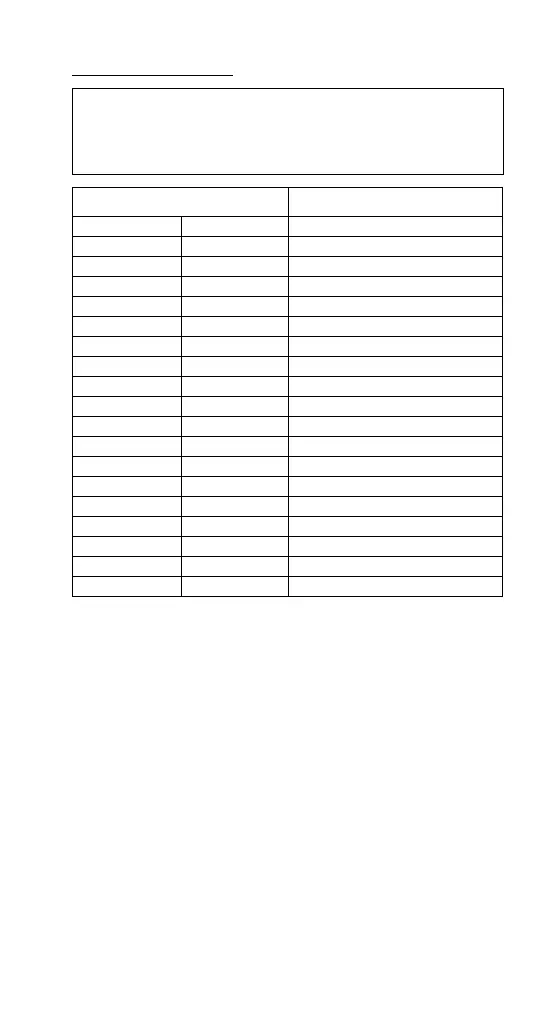
THERMISTOR CHART
Important
If the ohmmeter reads “OL,” check the scale setting on
the meter before assuming the thermistor is bad.
Temperature of Thermistor Resistance
-7 - -1.0 19 - 30 47.06 - 34.36
0.0 32 32.65
0.5 33 31.82
1.0 33.8 31.03
1.1 34 30.85
1.5 34.7 30.25
2.0 35.6 29.49
2.5 36.5 28.76
3.0 37 28.05
3.5 38 27.36
4.0 - 10.5 39 - 51 26.68 - 19.43
11.0 - 15.0 52 - 59 18.97 - 15.71
15.5 - 20.0 60 - 68 15.35 - 12.49
20.5 - 25.0 69 - 77 12.21 - 10.00
25.5 - 30.0 78 - 86 9.78 - 8.05
30.5 - 35.0 87 - 95 7.88 - 6.39
36.5 - 40.0 98 - 104 6.14 - 5.32
40.5 - 46.0 105 - 115 5.22 - 4.20
NOTE: The control board will default to a 3.75 minute
pump delay in the freeze cycle, whenever the thermistor is
disconnected or reads outside the resistance ranges in the
table.
 Loading...