10
SERVICING & CALIBRATION
CALIBRATION / INTERNAL ADJUSTMENTS - FOR EXPERIENCED TECHNICIANS ONLY*
The CORE requires calibraon for 3 secons of its circuitry:
1) VU METER- Adjust: +4dBu (1.228 Volts RMS) = “0” VU, Meter “GR” zero set
2) ELOP
®
COMPRESSOR - Adjust: Gain Reducon (Audio & Meter GR)
3) FET PEAK LIMITER - Adjust: reference voltage & FET control voltage
Tools required:
Audio Tone Generator (oscillator)
Audio Analyzer or a voltmeter capable of reading both DC & AC voltages.
Inial sengs:
Mic/Line Input select switch: Out = LINE IN Enable
120Hz HP lter switch: Out = Disable
Gain switch: Out = LOW
48V Phantom switch: Out = OFF
Phase Invert switch: Out = 0
Input Level Aenuator: Set at Minimum
Compressor Secon: Switch = Bypass, Compression = MAX, Aack & Release = FAST
Shelving EQ secon: High/Low controls set both = 12 o’clock.
Mid EQ secon: Boost/Cut control = 12 o’clock, Frequency range select switch = 100Hz-1kHz, Frequency sweep control = MIN
Peak Limiter secon: Liming = MIN, Release = 12 o’clock
Output Gain Control: 12 o’clock
*Experienced Technicians Only
The calibraon procedures
menoned here are to aid in the
servicing of the unit. They should
only be aempted by a skilled
technician. These adjustments
should not be aempted by the
user without experience. Trimming
these potenometers without the
correct understanding will result in
poor performance of the unit.
– connued on next page –
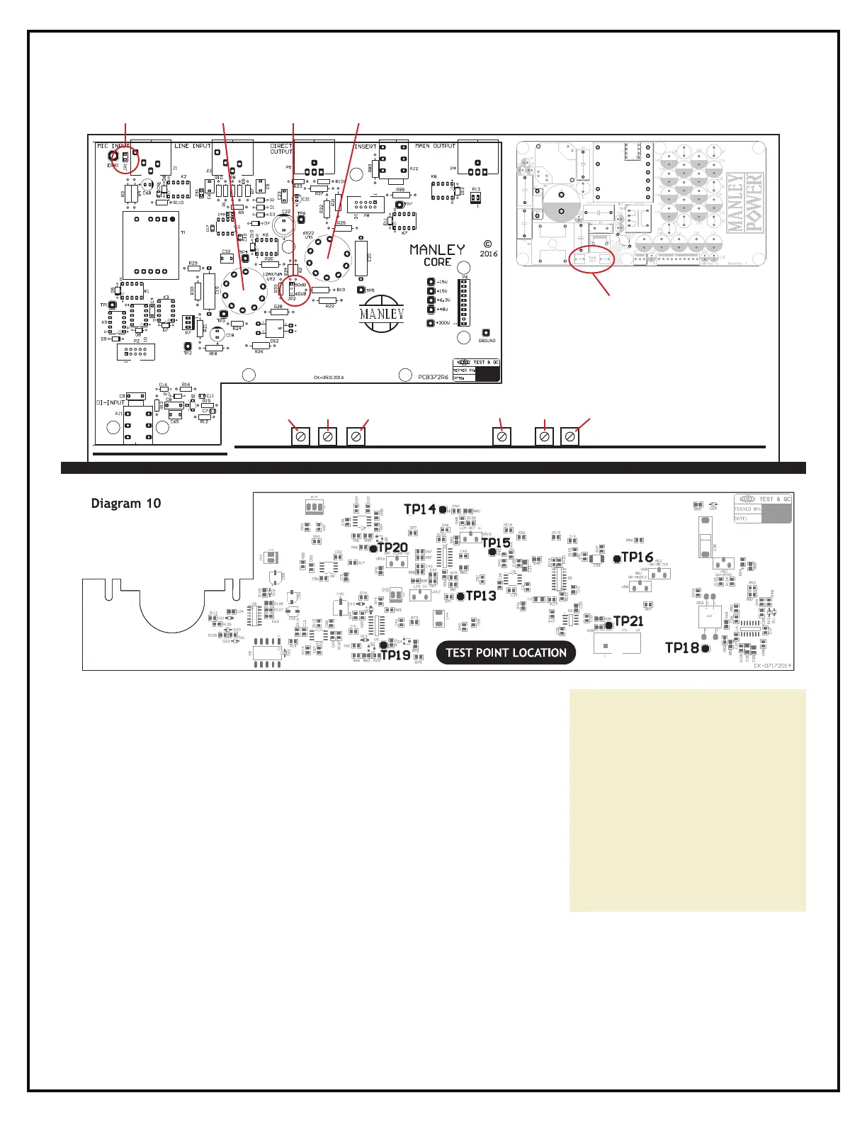
Diagram 9
GROUND LIFT
JUMPER
12AX7WA
GAIN JUMPER
6922
VR11
GR-ZERO LIM CVGR-METER LIM REF VGR-AUDIO OP1 ZERO VU
VR15
VR9
VR12
VR6
VR16
2 Amp Slow-Blow (T)
20mm Ceramic FUSE