8
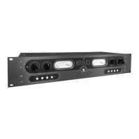
From Right to Le:
MIC INPUT: This is a transformer balanced, microphone input to the preamplier.
The pinout is PIN 1: Ground, PIN 2: HOT (+), PIN 3: COLD (-).
All pins must be driven. DO NOT “oat” PIN 2 or PIN 3.
LINE INPUT: An electronically-balanced, line-level input.
The pinout is PIN 1: Ground, PIN 2: HOT (+), PIN 3: COLD(-).
An unbalanced source can be connected with PIN2 or 3 grounded. Unused pins can be grounded.
DIRECT OUT (1): Gives an pseudo or impedance balanced output directly aer the tube preamp and ELOP® compressor stage.
The pinout is PIN 1: Ground, PIN 2: HOT (+), PIN 3: COLD (-).
An unbalanced input can be connected to this output with PIN3 grounded.
INSERT: This TRS 1/4” jack interrupts the connecon between the PREAMP/COMPRESSOR and EQ/FET LIMITER secons,
allowing external gear to be inserted into the signal path. Alternately, it provides an input to the CORE that is aer the tube
preamp, to the input of the EQ stage. The interface is unbalanced in and out.
The pinout is TIP: SEND, RING: RETURN, SLEEVE: GROUND.
OUTPUT (2): This is the main output from the CORE which is an electronically-balanced output. It is aer the EQ/Limiter
secon. The pinout is PIN 1: GROUND, PIN 2: HOT (+), PIN 3: COLD (-).
An unbalanced input can be connected to this output with PIN2 or 3 oated but DO NOT ground pin 2 or 3.
Unbalanced Operaon
All of the XLR inputs of the CORE can be used with either balanced or unbalanced sources. However, the Main (2) XLR
output should only be connected to balanced inputs. If it’s necessary to connect to a unbalanced input, a cable must be used
that has NO connecon on XLR pin 3. This is important in order to prevent damage to the CORE, as well as distoron to the
signal. DO NOT GROUND PINS 2 OR 3 on the MAIN O/P 2.
Geng the most from your CORE
Earlier, in the Introducon we menoned one of the three design principles was “Forgiving”. We want the CORE to be easy
to use and dicult to make a bad sound! An example of this is the placement of the compressor before the amplier stages.
This allows the signal to be reduced by the compressor rst which prevents the preamp from being overloaded. Seng the
COMPRESSION level just at the start of gain- reducon will allow you to get the full dynamic range of the source, but if the
musician suddenly plays louder the compressor will gracefully ride the level down.
Another forgiving element of the CORE is the FET output limiter which can be set to reduce just under the overload level of
the following piece of gear. This can be especially useful to protect an A/D converter from overload.
There is no rule that says you can’t put a line-level signal in the Mic input. Try it! Many dierent transformer or tube
saturaon eects can be made this way.
Just be careful not to engage the PHANTOM power 48V switch if yiou have anything other than a phantom-powered
microphone plugged into the MIC INPUT.
REAR PANEL CONNECTIONS
OPERATIONAL NOTES