EasyManuals Logo

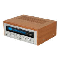
Marantz 2015 User Manual

Marantz 2015
23 pages
To Next Page IconTo Next Page
To Previous Page IconTo Previous Page
Page #3 background imageLoading...
Page #3 background image
INTRODUCTION
This
service
manual
was
prepared
for
use
by
Authorized
Warranty
Stations
and
contains
service
information
for
Marantz
Model
2015
Stereophonic
Receiver.
Servicing
information
and
voltage
data
included
in
this
manual
are
intended
for
use
by
the
knowledgeable
and
experienced
technician
only.
All
instruction
should
be
read
carefully.
No
attempt
should
be
made
to
proceed
without
a
good
understanding
of
the
operation
in
the
receiver.
The
parts
list
furnish
information
by
which
replacement
part
may
be
ordered
from
the
Marantz
Company.
A
simple
description
is
included
for
parts
which
can
be
usually
be
obtained
through
local
suppliers.
1.
Service
Notes
As
can
be
seen
from
the
circuit
diagram,
the
chassis
of
Model
2015
consists
of
the
following
units.
Each
unit
mounted
on
a
printed
circuit
board
is
described
within
the
square
enclosed
by
a
bold
dotted
line
on
the
circuit
diagram.
1
EM/AM
TUNeT
idee
ce
ot
on
dee
Pe
dict
swe
bi
had
ou
nesas
mounted
on
P.
W.
Board
P100
2.
MPX
Stereo
Indicator
....
0...
ccc
cee
ee
ees
mounted
on
P.
W.
Board
P200
3.
Phono
Amplifier
.....
0.0.0...
ccc
cee
ee
eee
eee
mounted
on
P.
W.
Board
P300
4.
Tape
Mon,
Mono,
Loudness
and
Muting
Switch
Unit
.......
mounted
on
P.
W.
Board
P400
5.
Tone
Amplifier
....
0...
cc
ce
eee
ee
eee
e
eee
e
nes
mounted
on
P.
W.
Board
P500
6.
Power
Amplifier
.......
00.0...
ccc
eee
eee
sea
aha
mounted
on
P.
W.
Board
P600
7.
Temperature
Compensation
unit
...........
0.020
e
ees
mounted
on
P.
W.
Board
P700
8.
Power
Supply
.......
00.
cc
eee eee
eee
eee
ete
eens
mounted
on
P.
W.
Board
P800
2.
AM
Tuner
All
components
except
ferrite
bar
antenna
are
mounted
on
a
printed
circuit
board
P100.
The
AM
signals
induced
in
a
ferrite
bar
antenna
are
applied
to
the
base
of
converter
transistor
H113
through
a
capacitor
of
C171,
while
the
local
oscillator
voltage
is
injected
to
the
emitter
of
H1i13
through
a
capacitor
C172.
Both
AM
signals
and
oscillating
voltage
are
mixed
at
the
base-emitter
junction
and
converted
into
455KHz
intermediate
frequency.
The
resulting
IF
signal
is
applied
to
the
first
IF
transformer
L116
consisting
of
one
ceramic
filter
and
two
tuned
circuits.
The
output
of
L116
is
led
to
the
transistor
H104
which
in
turn
apply
its
output
to
the
transistor
of
next
stage
H105.
The
fully
amplified
[IF
output
is
then
applied
to
the
diode
H123
to
detect
audible
signa!
through
the
detector
transformer
L117.
The
detected
audio
signa!
is
filtered
and
the
final
audio
output
is
obtained
from
the
pin
terminal
J118
and
applied
to
the
func-
tion
switch.
The
DC
component
of
the
detected
IF
signal
is
used
as
a
AGC
voltage
to
control
emitter
current
of
H104
through
the
resistor
R185.
A
part
of
IF
signal
output
is
also
applied
to
the
diode
H124
through
a
capacitor
C180
and
rectified
to
obtain
DC
current
for
energizing
the
AM
signal
strength
meter
M001.
2.1
Suggestions
for
AM
Tuner
trouble
shooting
Check
for
broken
AM
bar
antenna,
next
try
to
tune
station
by
rotating
fly-wheel
tuning
knob
slowly
and
observe
the
AM
signal
strength
meter
whether
it
deflects
or
not.
If
the
signal
strength
meter
gives
a
deflection
at
several
frequencies
received,
no
failure
may
exist
in
the
stages
at
least
preceding
final
IF
transformer
L117.
Next
connect
a
oscilloscope
to
the
pin
terminal
J118
and
check
for
audio
signals
with
the
tuning
meter
deflected.
If
the
signal
strength
meter
does
not
deflect,
check
the
local
oscillator
circuit.
Normal
oscillating
voltage
at
the
hot
end
of
the
oscillator
tuning
capacitor
is
about
2
or
3
volts,
varying
with
tuning
capacitor
position.
When
measuring
oscillating
voltage
use
a
RF
VTVM,
no
circuit
tester
gives
correct
indication.
If
the
local
oscillator
voltage
is
normal,
check
all
voltage
distribution
in
the
AM
circuits
by
using
a
DC
VTVM
and
compare
the
measured
values
with
those
given
in
the
schematic
diagram.

Other manuals for Marantz 2015

Questions and Answers:

Question and Answer IconNeed help?

Do you have a question about the Marantz 2015 and is the answer not in the manual?

Marantz 2015 Specifications

General IconGeneral
Power Output15 watts per channel into 8Ω (stereo)
Frequency Response20Hz to 20kHz
Total Harmonic Distortion0.8%
Input Sensitivity2.2mV (MM), 180mV (line)
Tuning RangeFM, MW
Speaker Load Impedance4Ω to 16Ω
OutputHeadphones

Related product manuals