Do you have a question about the Marantz 6350 and is the answer not in the manual?
Details the sequence of operations for the automatic play and shut-off functions.
Explains the manual control sequence for starting, stopping, and raising the tone arm.
Procedures for verifying and correcting the automatic shut-off mechanism at different speeds.
Introduces essential tone arm adjustments for optimal turntable performance.
Guidance on setting the stylus pressure for accurate record playback.
How to set the anti-skating force to counteract record groove forces.
Method for checking and ensuring the correct stylus tracking angle.
Instructions for adapting the unit's power supply for various international voltages.
Standard color coding for tone arm cartridge lead connections.
Contact information for ordering parts and obtaining technical support.
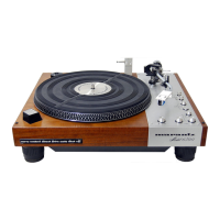
Identifies major components visible on the top surface of the turntable.
Identifies major components located on the rear panel of the turntable.
Illustrates the placement of major components on the underside of the cabinet.
Shows the location of internal chassis components from the bottom perspective.
Provides the schematic and component layout for the P800 Power Supply Assembly.
Schematic and component layout for the PV02 Adjuster Assembly.
Schematic and component layout for the PV01 Adjuster Assembly.
Schematic and component layout for the PV03 Connective Assembly.
| Speeds | 33 1/3 and 45 rpm |
|---|---|
| Tonearm | Static Balance Type |
| Overhang | 15 mm |
| Platter | Die-cast aluminum |
| Wow and Flutter | 0.05% WRMS |