10
ENGLISH
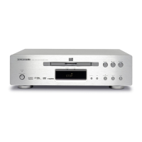
Rear Panel
OUTPUT
DIGITAL
OUTPUT
VIDEO
C
Y
COMPONENT
OUTPUT
AUDIO
OPTICAL
CONTROL
REMOTE
1L
R
B
R2
C
INTERNALEXTERNAL
COAXIAL
OUT
IN
12
VIDEO
S2
q w e r t y !0 !11
VIDEO OUTPUT
COMPONENT
VIDEO/S2
TV SYSTEM
AUTO
NTSCPAL
i ou
q Analog audio out (L/R) jacks
(Page 12, 13)
w Video out jacks (Page 12, 14)
e S Video out jack (Page 14)
r COMPONENT Video out jacks
(Y/CB/CR) (Page 14)
t BITSTREAM/PCM Coaxial digital
audio out jack (Page 13)
y BITSTREAM/PCM Optical digital audio
out jack (Page 13)
u REMOTE Control in/out jacks (Page 14)
i TV SYSTEM switch (Page 15)
o Video output selector (Page 14)
!0 REMOTE Control external/internal switch
(Page 14)
!1 Power cord
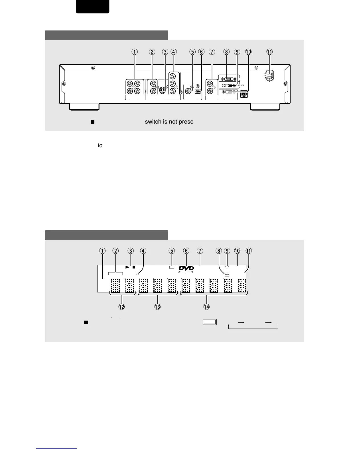
Display Window
q 96 kHz indicator
w VIDEO OFF indicator
e Operating status indicator
r Remote Control indicator
t DTS indicator
y DVD indicator
u (V) CD indicator
i Camera Angle indicator
o CHAPTER/TITLE/TRACK Repeat
indicators
!0 LAST MEMO indicator
!1 Condition MEMO indicator
!2 TITLE number indicator
!3 CHAPTER/TRACK number indicator
!4 TOTAL/TRACK TIME indicators
Pressing of the DIMMER button
changes the brightness of the display.
DIMMER
Normal Dimmed OFF
VCD
REMAIN
CONDITION
TOTALTITLE TRACK
VIDEO OFF
dts
96KHz
LAST MENO
CHP
!0ouytr iewq
!2 !3
!1
!4
The TV SYSTEM switch is not present on the USA model.
 Loading...