EasyManua.ls Logo

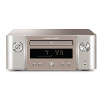
Marantz M-CR611/U1B User Manual

Marantz M-CR611/U1B
111 pages
To Next Page IconTo Next Page
Page #1 background imageLoading...
Page #1 background image
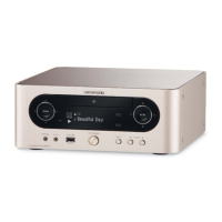
NETWORK CD RECEIVER
M-CR611 /
U1B/N1B/K1B
/FN
M-CR611
S1315V04DM/DG1607
Copyright 2016 D&M Holdings Inc. All rights reserved.
WARNING: Violators will be prosecuted to the maximum extent possible.
Ver. 4
•
Some illustrations using in this service manual are slightly different from the actual set.
•
Please use this service manual with referring to the operating instructions without fail.
•
For purposes of improvement, specications and design are subject to change without notice.
Please refer to the
MODIFICATION NOTICE.
Service
Manual
Table of Contents

Questions and Answers:

Marantz M-CR611/U1B Specifications

General IconGeneral
TypeNetwork CD Receiver
CD PlayerYes
Input Sensitivity200 mV
Audio Formats SupportedMP3, WMA, AAC, ALAC, WAV, FLAC, AIFF
Network ConnectivityWi-Fi, Ethernet
BluetoothYes
Streaming ServicesSpotify
Radio TunerFM
USBYes
Remote ControlYes

Summary

About This Manual

What you can do with this manual

Explains how to use the manual's search function and features within Adobe Reader for efficient navigation.

Jump to schematic diagram connectors

Instructions on how to navigate to specific schematic diagram connectors using reference numbers.

Using Adobe Reader Features

Add notes to this data (Sign)

Details on using the 'Sign' function in Adobe Reader to add annotations to the manual.

Magnify schematic / circuit board diagrams

Instructions on magnifying schematic and printed circuit board diagrams using keyboard and mouse.

Print a magnified part of the manual

Guide on configuring print settings to output specific magnified sections of the manual.

Magnify schematic / circuit board diagrams (Pan & Zoom)

Using the Pan & Zoom function to view specific parts of magnified diagrams in a separate window.

Magnify schematic / circuit board diagrams (Loupe Tool)

Using the Loupe Tool function to magnify specific parts of diagrams in a separate window.

Safety Precautions

Cautions during servicing and inspection

Essential cautions for safe servicing and inspection procedures, including electric shock and disassembly warnings.

Important safety parts

Highlights the importance of using designated parts with specific safety properties for repairs.

Handling Semiconductors and Optical Unit

Ground for Human Body

Instructions for grounding the human body with a 1 MΩ band to prevent static discharge.

Ground for Workbench

Guidelines for grounding the workbench with a conductive sheet to prevent static discharge.

Laser Safety

Technical Specifications

Audio section

Detailed specifications for the audio amplifier, CD player, and input sensitivity.

Tuner section

Specifications for the FM/AM tuner, including receiving range and sensitivity.

DAB tuner section

Specifications for the DAB tuner, including receiving range and sensitivity.

Wireless LAN section

Specifications for the wireless LAN standard, security, and radio frequency.

Bluetooth section

Specifications for the Bluetooth system, including version, transmission power, and supported profiles.

Clock / Alarm / Sleep

Specifications for the clock, alarm, and sleep timer functions.

General

General specifications including power supply and power consumption details.

Dimension

Caution in Servicing

Initializing This Unit

Procedure for unit initialization after replacing critical components like the microcomputer.

Service tools

Lists specific service tools required for measurements and diagnostics.

Replacing the WLAN MODULE with a new one

Step-by-step guide for replacing the WLAN MODULE and ensuring firmware updates.

Removing the AMP PCB from the MAIN PCB

Disassembly

Top Panel Disassembly

Procedure for disassembling the top panel, including screw and connector removal.

Front Panel Assy Disassembly

Procedure for disassembling the front panel assembly, including screws and wires.

CD Mecha Assy Disassembly

Procedure for removing the CD Mecha assembly, including connector wires and FFC.

Mecha Support L/R Disassembly

Instructions for removing the Mecha Support L/R, referencing the exploded view.

Tuner Disassembly

Instructions for removing the Tuner component, referencing the exploded view.

Explanatory Photos for Disassembly

Viewpoint of each photograph

Illustrates the shooting directions (A, B, C, D) used in the disassembly photographs.

Special Mode

Factory Update Mode

Mode used for overwriting firmware during production, not for servicing.

Version Display Mode

Mode to display the unit's firmware version information.

CD Test Mode

Mode for servo adjustment and laser current measurement.

USB Update Mode

Switches the unit to USB update mode for firmware.

User Initialization Mode

Initializes settings, differing from factory reset by retaining version info and protection history.

Factory Initialization Mode

Initializes all setting values to factory defaults, clearing logs and protection history.

Protection History Display Mode

Displays the unit's protection occurrence history, such as thermal or speaker protection.

Procedure After Replacing Microprocessor

Procedure after Replacement

Details the software writing procedure after replacing the u-COM, flash ROM, or CY920 MODULE.

Firmware Update Procedure

Updating via USB

Procedure for downloading the latest firmware via USB memory.

Connecting to the USB Memory

Preparation steps for connecting a USB memory device for firmware updates.

Unzipping the Downloaded File

Instructions for unzipping the firmware file and copying the 'firmwares' folder.

File structure on USB Memory

Specifies the required file structure for the update files on the USB memory.

Start the update

Steps to initiate the firmware update process via USB.

Forced USB All Device Write Mode

Update Procedure in Event of CY920 Error

Updating via DPMS

Network Connection

System requirements for updating firmware via DPMS over a network connection.

Check and update the firmware

Procedure to check for and initiate firmware updates through the unit's menu.

Error Code Table

DPMS Update Error Codes

Lists error codes for DPMS update events and their corresponding FL messages.

CX920 Error Codes

Lists error codes related to CX920 firmware rewriting and their FL messages.

Trouble Shooting

OLED does not light

Diagnostic steps and checks for troubleshooting when the OLED display is not lighting up.

No Sound or Noise Generated

Troubleshooting steps for issues related to lack of sound or unwanted noise.

COMMON (Signal)

Troubleshooting steps related to common signal paths, including digital audio data.

COMMON (Power Control Signal)

Troubleshooting steps for power control signals affecting unit operation.

CD Playback Issues

Troubleshooting steps specifically for problems encountered during CD playback.

Tuner Troubleshooting (U/F/K)

Diagnostic steps for tuner issues specific to U, F, and K regions.

Tuner Troubleshooting (N)

Diagnostic steps for tuner issues specific to the N region.

Analog Input Troubleshooting

Troubleshooting steps for analog audio input signals.

Digital Input Troubleshooting

Troubleshooting steps for digital audio input signals.

USB / ETHERNET / Wi-Fi Troubleshooting

Diagnostic steps for connectivity issues related to USB, Ethernet, and Wi-Fi.

Analog Audio Output Troubleshooting

Troubleshooting steps for problems with analog audio output signals.

Measuring Method and Waveforms

Test Points

Identifies key test points on the MAIN PWB and CD PWB for waveform measurement.

Waveforms

Illustrates expected waveforms for disc play, TOC read, and focus adjustment.

Block Diagram

Power Diagram

Wiring Diagram

Printed Circuit Boards

Schematic Diagrams (1/10) SCH01_MAIN_MCU_PWM

Schematic Diagrams (2/10) SCH02_MAIN_NETWORK

Schematic Diagrams (3/10) SCH03_MAIN_DAB

Schematic Diagrams (4/10) SCH04_CNT

Schematic Diagrams (5/10) SCH05_NFC

Schematic Diagrams (6/10) SCH06_AMP_611

Schematic Diagrams (7/10) SCH07_FRONT_611

Schematic Diagrams (8/10) SCH08_INPUT

Schematic Diagrams (9/10) SCH09_CD

Schematic Diagrams (10/10) SCH10_SMPS

Exploded View

Decoration Parts

List of decorative parts for the unit's exterior.

Window Parts

List of window components, including loader and display parts.

Cover Parts

List of various cover components for the unit.

Panel Parts

List of panel components, including front and top panels.

Button Assembly Parts

List of button assembly components, including input and power buttons.

Reflector Parts

List of reflector components used in the unit.

Plate Parts

List of plate components used in the assembly.

Display Parts

List of display unit components.

Holder Parts

List of holder components for various parts.

Case Parts

List of case components for the unit.

Chassis Parts

List of chassis components for the unit assembly.

Packing View

Sheet Packing Materials

List of sheet materials used for packing the unit.

Poly Bag Packing Materials

List of poly bags used for packing the unit.

Cushion Packing Materials

List of cushion materials used for packing the unit.

Tape Packing Materials

List of tapes used for packing the unit.

Label Packing Materials

List of labels used for packing the unit.

Documentation for Packing

List of documentation included in the packing, such as warranty cards and manuals.

Semiconductors

ICs

Overview of major integrated circuits used in the unit.

IC Pin Descriptions

Detailed pin descriptions and functions for key ICs like R5F56108VNFP.

TC94A92FG (CD : IC701)

TC94A92FG Block Diagram

Block diagram illustrating the internal functions of the TC94A92FG IC.

TC94A92FG Terminal Function

Detailed description of each terminal function for the TC94A92FG IC.

IP4001CR (CD : IC702)

IP4001CR Block Diagram

Block diagram of the IP4001CR 5-channel motor drive IC.

IP4001CR Pin Descriptions

Detailed description of each pin for the IP4001CR IC.

PCM9211 (MAIN : IC107)

PCM9211 Block Diagram

Block diagram of the PCM9211 digital audio interface transceiver IC.

PCM9211 Pin Functions

Detailed description of each pin function for the PCM9211 IC.

NJM2752 (INPUT : IC2)

NJM2752 Pin Assignments and Functions

Pin assignments and functional descriptions for the NJM2752 audio selector IC.

NJM2755 Block Diagram

Block diagram for the NJM2755 audio selector IC.

TAS5142DKD (AMP : IC500, IC502)

TAS5142 Pin Descriptions

Detailed pin descriptions for the TAS5142 digital amplifier IC.

TAS5142 Block Diagram

Block diagram of the TAS5142 digital amplifier IC.

TAS5558 (MAIN : IC108)

TAS5558 Pin Descriptions

Detailed pin descriptions for the TAS5558 PWM processor IC.

TAS5558 Block Diagram

Block diagram of the TAS5558 PWM processor IC.

EN5339QI (NETWORK : IC803, IC804, IC806, IC807)

EN5339QI Pin Discriptions

Pin descriptions for the EN5339QI DC-DC converter IC.

EN5339QI Block Diagram

Block diagram of the EN5339QI DC-DC converter IC.

MX25L25635FMI (NETWORK : IC812)

MX25L25635FMI Pin Discriptions

Pin descriptions for the MX25L25635FMI flash memory IC.

MX25L25635FMI Block Diagram

Block diagram of the MX25L25635FMI flash memory IC.

BD11600NUX (NETWORK : IC809, IC810)

BD11600NUX Block Diagram

Block diagram of the BD11600NUX USB switch IC.

BD11600NUX Pin Discriptions

Pin descriptions for the BD11600NUX USB switch IC.

TPS2065CDBVR (NETWORK : IC800, IC811)

TPS2065CDBVR Block Diagram

Block diagram of the TPS2065CDBVR power switch IC.

TPS2065CDBVR Pin Discriptions

Pin descriptions for the TPS2065CDBVR power switch IC.

FL6300A (SMPS : IC821)

FL6300A Block Diagram

Block diagram of the FL6300A SMPS controller IC.

FL6300A Pin Discriptions

Pin descriptions for the FL6300A SMPS controller IC.

ICE3BR1765J (SMPS : IC871)

ICE3BR1765J Block Diagram

Block diagram of the ICE3BR1765J SMPS controller IC.

ICE3BR1765J Pin Description

Pin description for the ICE3BR1765J SMPS controller IC.

tps54340 (SMPS : IC441)

tps54340 Pin Discriptions

Pin descriptions for the tps54340 SMPS controller IC.

tps54340 Block Diagram

Block diagram of the tps54340 SMPS controller IC.

Display

STA309A_ST (MAIN : IC102)

STA309A_ST Block Diagram

Block diagram of the STA309A_ST audio processor IC.

STA309A_ST Pin Description

Detailed pin description for the STA309A_ST audio processor IC.

Main PCB Assembly Parts

Semiconductors Group

List of semiconductor components for the main PCB.

Resistor Group

List of resistors for the main PCB.

Capacitors Group

List of capacitors for the main PCB.

Other Parts Group

List of miscellaneous parts for the main PCB assembly.

Front PCB Assembly Parts

Semiconductors Group

List of semiconductor components for the front PCB.

Resistor Group

List of resistors for the front PCB.

Capacitors Group

List of capacitors for the front PCB.

Other Parts Group

List of miscellaneous parts for the front PCB assembly.

AMP PCB Assembly Parts

Semiconductors Group

List of semiconductor components for the AMP PCB.

Resistor Group

List of resistors for the AMP PCB.

Capacitors Group

List of capacitors for the AMP PCB.

Other Parts Group

List of miscellaneous parts for the AMP PCB assembly.

CD PCB Assembly Parts

Semiconductors Group

List of semiconductor components for the CD PCB.

Resistor Group

List of resistors for the CD PCB.

Capacitors Group

List of capacitors for the CD PCB.

Other Parts Group

List of miscellaneous parts for the CD PCB assembly.

Input PCB Assembly Parts

Semiconductors Group

List of semiconductor components for the Input PCB.

Resistor Group

List of resistors for the Input PCB.

Capacitors Group

List of capacitors for the Input PCB.

Other Parts Group

List of miscellaneous parts for the Input PCB assembly.

NFC PCB Assembly Parts

Semiconductors Group

List of semiconductor components for the NFC PCB.

Resistor Group

List of resistors for the NFC PCB.

Capacitors Group

List of capacitors for the NFC PCB.

Other Parts Group

List of miscellaneous parts for the NFC PCB assembly.

CNT PCB Assembly Parts

Capacitors Group

List of capacitors for the CNT PCB.

Other Parts Group

List of miscellaneous parts for the CNT PCB assembly.

Exploded View

Decoration Parts

List of decorative parts for the unit's exterior.

Window Parts

List of window components, including loader and display parts.

Cover Parts

List of various cover components for the unit.

Panel Parts

List of panel components, including front and top panels.

Button Assembly Parts

List of button assembly components, including input and power buttons.

Reflector Parts

List of reflector components used in the unit.

Plate Parts

List of plate components used in the assembly.

Display Parts

List of display unit components.

Holder Parts

List of holder components for various parts.

Case Parts

List of case components for the unit.

Chassis Parts

List of chassis components for the unit assembly.

Packing View

Sheet Packing Materials

List of sheet materials used for packing the unit.

Poly Bag Packing Materials

List of poly bags used for packing the unit.

Cushion Packing Materials

List of cushion materials used for packing the unit.

Tape Packing Materials

List of tapes used for packing the unit.

Label Packing Materials

List of labels used for packing the unit.

Documentation for Packing

List of documentation included in the packing, such as warranty cards and manuals.

Related product manuals