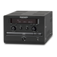
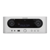
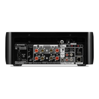
EasyManua.ls Logo

Marantz CR401 Service Manual

Marantz CR401
52 pages
To Next Page IconTo Next Page
Page #1 background imageLoading...
Page #1 background image
CR401
Please use this service manual with referring to the user guide ( D.F.U. ) without fail.
Service
Manual
CR401
CD Receiver
CR401 /
N1S
Part no. 90M49BW855010
First Issue 2005.12
MZ
TABLE OF CONTENTS
SECTION PAG E
1. TECHNICAL SPEC I FI CA TIONS ........................................................................................... 1
2. SERVICE HINTS AND TOOLS ............................................................................................. 4
3. WARNING AND LASER SAFETY IN STRUC TIONS ............................................................. 5
4. TAKING THE DISC OUT OF EMERGENCY ........................................................................ 6
5. CD UPDATE FIRMWARE ...................................................................................................... 7
6. FACTORY / SERVICE MODE ............................................................................................... 8
7. WIRING DIAGRAM ............................................................................................................... 9
8. BLOCK DIAGRAM ..............................................................................................................11
9. SCHEMATIC DIAGRAM ...................................................................................................... 13
10. PARTS LOCATION .............................................................................................................. 19
11. MICROPROCESSOR AND IC DATA ................................................................................... 29
12. EXPLODED VIEW AND PARTS LIST ................................................................................. 41
13. ELECTRICAL PARTS LIST ................................................................................................. 44
STANDBY
STANDBY
PHONES
PHONES
POWER ON / STANDBY
POWERON/STANDBY
CD RECEIVER CR401
CD RECEIVER CR401
PUSH TO ENTER
PUSH TO ENTER
VOLUME
VOLUME
TREBLE
TREBLE
BASS
BASS
INPUT
INPUT
MENU
MENU
DIRECT
DIRECT

Other manuals for Marantz CR401

Questions and Answers:

Marantz CR401 Specifications

General IconGeneral
Remote ControlYes
Power Output4 x 50 Watts
TunerFM/AM
BluetoothYes
USB PortYes
AUX InputYes
Preamp OutputYes
DisplayLCD

Summary

Marantz Design and Service Information

Shock and Fire Hazard Service Test

Safety test procedure to measure resistance between primary AC cord pins and product chassis.

1. Technical Specifications

Amplifier Section Specifications

Technical details for amplifier output, distortion, input sensitivity, and frequency response.

About Discs and Compatibility

MP3 Compatibility Requirements

Specific requirements for MP3 file format, bit-rate, naming, and disc structure for playback.

2. Service Hints and Tools

Service Hints and Precautions

General advice on component handling, soldering techniques, and common service procedures.

3. Warning and Laser Safety Instructions

ESD and General Repair Warnings

Important warnings regarding electrostatic discharge (ESD) and general handling precautions during repair.

Laser Safety and Exposure Warning

Critical safety information about laser radiation exposure and handling of laser-equipped components.

5. CD Update Firmware

6. Factory and Service Mode

Factory Mode: Resetting Settings

Procedure to reset all unit settings to their default factory state.

Service Mode: Version Check

Instructions for entering service mode to check system, CD, and DAB micro-processor versions.

7. Wiring Diagram

8. Block Diagram

9. Schematic Diagram

10. Parts Location

11. Microprocessor and IC Data

IC102: µPD78F0536 Pinout and Data

Detailed pinout and functional data for the µPD78F0536 microprocessor.

IC201: CXA2581N Block Diagram

Block diagram illustrating the internal functions and signal paths of the CXA2581N IC.

IC201: CXA2581N Pinout and Functions

Pinout and description for the CXA2581N IC, detailing its input/output functions.

12. Exploded View and Parts List

13. Electrical Parts List

Related product manuals