Do you have a question about the Marantz MM7055/N1B and is the answer not in the manual?
Information required for ordering Marantz parts to avoid delays.
Key safety guidelines including leakage current checks and general servicing cautions.
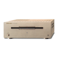
Detailed technical specifications for the MM7055 amplifier.
Diagrams showing the physical external dimensions of the unit.
Overview of the disassembly sequence for major unit assemblies.
Detailed steps for disassembling Front Panel, CPU, Trans, STBY, Input, Power, and Amp units.
Accessing and using Service Mode for protection log and exit.
Using Factory Mode for FAN, AVSS, destination, standby, and initialization.
Checking CPU version and interpreting protection logs via LEDs.
Understanding LED patterns for error detection and reasons.
Specific points to check for each detected system error.
Steps for replacing the microprocessor and updating CPU software.
Steps to adjust idling current using VRs and measurement points.
Diagnosing and resolving power-on failures and blown fuses.
Troubleshooting no audio output and power amplifier PCB problems.
Block diagrams of major unit sections like Audio, CPU, Power.
Component layouts for Front, CPU, AMP, Input, Power, and Standby PCBs.
Diagram illustrating the wiring connections between all major PCBs and components.
Exploded view and list of main unit components.
Detailed specifications for ICs, EEPROMs, sensors, and transistors.
Parts lists for Front, AMP, Input, and Power PCB assemblies.
| Channels | 5 |
|---|---|
| Type | Power Amplifier |
| Signal-to-Noise Ratio | 110 dB |
| Input Sensitivity | 1.2 V |
| Damping Factor | 100 |
| Power Output (8 ohms) | 140 W |
| Frequency Response | 8 Hz - 100 kHz |
| Dimensions (W x H x D) | 440 x 128 x 384 mm |