Do you have a question about the Marantz PM-16FN and is the answer not in the manual?
Details required information for parts orders and provides international service contact information.
Critical safety warning regarding resistance checks after servicing to prevent electrical hazards.
Presents the unit's technical specifications and the overall system block diagram for understanding.
Detailed schematic diagrams showing circuit layouts and component locations for service.
Provides an exploded view of the unit and a comprehensive list of parts for maintenance.
Lists required test equipment and details the procedure for idling current adjustment.
Details electrical parts, component code assignments, abbreviations, and critical safety precautions for replacement.
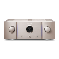
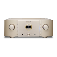
This document is a comprehensive service manual for the Marantz PM-16FN Integrated Amplifier, identified by model number 74 PM16/02B/02G. It provides detailed information for technicians and service personnel to effectively maintain, troubleshoot, and repair the device.
The Marantz PM-16FN is an integrated amplifier designed to deliver high-fidelity stereo sound. Its core function is to receive audio signals from various sources, amplify them, and output them to loudspeakers. The amplifier features multiple input options, allowing users to connect a range of audio components such as CD players, turntables (with dedicated phono inputs for both MM and MC cartridges), tape decks, and other line-level sources. It also includes a headphone output for private listening.
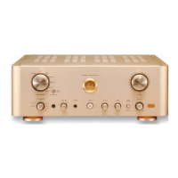
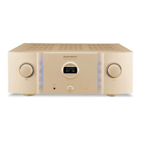
The amplifier's design emphasizes superior sound quality, achieved through the use of high-grade components and Marantz's proprietary design principles. It incorporates a sophisticated input selector and recording selector, enabling users to manage multiple audio sources and direct signals for recording. The inclusion of tone controls (bass and treble) allows for sound customization, while a balance control helps adjust the stereo image. A direct switch bypasses the tone and balance controls for a purer audio path.
The power amplifier section is designed for robust performance, providing ample power to drive loudspeakers effectively. Protection circuits are integrated to safeguard the amplifier and connected speakers from potential damage due to overcurrent or other anomalies. The unit also features a power supply section that ensures stable and clean power delivery to all internal circuits, crucial for maintaining audio integrity.
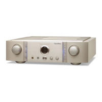
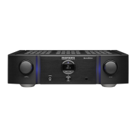
The PM-16FN is designed for user-friendly operation, with a clear and intuitive front panel layout. The master volume control is prominently featured, allowing for easy adjustment of the overall output level. Input selection is managed through a dedicated selector, typically a rotary knob or push buttons, enabling seamless switching between connected audio sources.
For vinyl enthusiasts, the amplifier includes a phono input with a selectable MM/MC switch, accommodating different types of phono cartridges. This flexibility ensures optimal performance with a wide range of turntables. The recording selector allows users to choose which input source is routed to a connected recording device, offering versatility for audio archiving or dubbing.
The amplifier's front panel also features controls for tone adjustment (bass and treble) and balance, giving users the ability to fine-tune the sound to their preference and listening environment. A "Source Direct" or similar function is typically available to bypass these tone controls, providing a more direct signal path for purist listening. A headphone jack is conveniently located for private listening sessions.
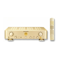
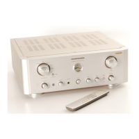
The remote control unit (RMC-16PM), specified as an accessory, enhances convenience by allowing users to operate key functions of the amplifier from a distance. This includes power on/off, volume adjustment, and input selection.
This service manual is a critical resource for maintaining the Marantz PM-16FN. It provides a structured approach to servicing, starting with a table of contents that outlines various sections.
The manual also includes contact information for Marantz subsidiaries and agents in various regions (USA, Canada, Europe, Australia, Hong Kong, Thailand, Taiwan, Malaysia, Singapore, and Japan), facilitating parts ordering and technical support. A "Shock, Fire Hazard Service Test" is outlined, requiring resistance measurements between AC cord pins and the chassis/front panel to ensure electrical safety before returning the unit to a customer. This comprehensive approach ensures that the PM-16FN can be maintained to its original performance and safety standards throughout its lifespan.
| Total Harmonic Distortion | 0.008% |
|---|---|
| Signal-to-Noise Ratio | 106 dB (CD) |
| Dimensions | 458 x 130 x 364 mm |
| Weight | 15 kg |
| Power Output | 100 W (8 ohms) |
| Input sensitivity | 200mV |