EasyManua.ls Logo

Marantz PM-17 User Manual

Marantz PM-17
17 pages
To Next Page IconTo Next Page
Page #1 background imageLoading...
Page #1 background image
74
PM17
/o1cio2c
PM-17F
n
Integrated
amplifier
TABLE
OF
CONTENTS
SECTION
PAGE
Die
ES
IA
ONG
iia
eadara
tet
sstrsaasuetare
anette
etna
lepetsctnlol
Austere
Ne
tas
Seen
aa
sete
ieee
1
IS
2:
FESTEQUIPMENT
REQGURED
FOR
SERVICING
scciviua
ce
cileecerautavescisencsaveacyestvendosadedeeieeagvias
Giaseene
at
FrHE
ACHES
AIS
ss
Be
I
OT
a
IW
tatecsett
can
tees
oacataeh
pad
acct
cao
arias
ace
a
eater
arse
oe
eect
amen
eee
oes
anette
etc
raat
tet
a
aeste
na
2
DZOWONRAP
ODL
4.
SCHEMATIC
DIAGRAM
AND
PARTS
LOCATIONS
(
PATTERN
SIDE
)...eccce
ee
eccecccccccseceeceseaeeeees
3
OBMWc
RRM
ONR-Y
Al)
Oy
Se
OD
VIE
VV
TAIN
DS
oat
etee
hates
rca
tetedeh
ene
didaeys
wenetnveiaaiams
ends
Sousa
Vacdsauesesdelosidtesds
11
Ty
REMC
Box
Or.
“DG
-
OPESEL.
VOLTAGE
Alt
INI
EN
i
ocaceks
sarc
cicdices
ta
tiacunddni
saan
ce,pedtevidsavcheaasddeueevat
tens
fut
seenuadediceee
14
DC
AVLY
KBE
RS
fe
4ADLING
CURRENT
ADIJUS
EMEN
PT
siic
steed
ocieeceris
sadscceeiai
cessdeacdauayiae
beads
oxdabeien
saddiuadatesScnscdvserecesue
tees
14
P4RUY
OS
RAS
SIIB
AM
5)
ww
1
Oy
4
Dea
2
ra
te
1
<8
Re
a
CIT
Te
15
Mab
cox
Please
use
this
service
manual
with
referring
to
the
user
guide
(
D.F.U.
)
without
fail.
(EHROEMA.
BO
RSs
Se
22
SL
IRE
OB
ERO
LER
IT
TSS)
RIE
Oa
a
RN
POON
III
OI
AIT
IIIT
I
EL
LN
CE
ELE
EN
SONIC
IEEE
EE
SNE
LIISA
model
PM-17
DATABASE
LAID
DEAD
ANA
IE
TIOOOO
SIL
IRIEL
IIAP
III
PIO
I
ORO
CII
4822
725
51138
First
issue
:
1997.
07
2693855010
AO
Question and Answer IconNeed help?

Do you have a question about the Marantz PM-17 and is the answer not in the manual?

Marantz PM-17 Specifications

General IconGeneral
Damping Factor100
TypeIntegrated Amplifier
Power Output60W (8 ohms, 20Hz-20kHz)
Frequency Response5Hz - 100kHz (+0dB, -3dB)
Signal to Noise Ratio106dB
Input Sensitivity200mV/20kOhm (Line)
Total Harmonic Distortion0.01% (20Hz-20kHz)
Channel Separation70dB

Summary

Marantz Product Design and Service Philosophy

Marantz Parts Ordering Procedure

Guidelines for ordering genuine Marantz replacement parts, specifying required information for accuracy.

Critical Safety Notice: Electrical Hazard

Essential warning about potential electrical shock and fire hazards after unit servicing.

Technical Specifications and Performance Data

Audio Performance Metrics

Comprehensive list of audio specifications including output, distortion, and frequency response.

Service and Maintenance Essentials

Required Servicing Equipment

List of necessary tools and measurement devices for performing maintenance on the amplifier.

System Architecture Block Diagram

Block diagram illustrating the overall system architecture and major functional units.

Microprocessor Control Logic

Detailed block diagram of the microprocessor and its associated control circuitry.

Circuit Diagrams and Component Layout

Input and Signal Path Schematics

Circuit diagrams for input selection, phono, and line stages, including signal flow.

Power Amplifier and Control Section Schematics

Circuit diagrams for the power amplifier stage and system control logic.

Component Identification and Assembly

Front Panel Assembly Breakdown

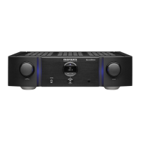
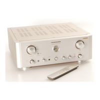
Visual breakdown of the front panel components for identification and replacement.

Internal Unit Assembly Exploded View

Exploded view of the main internal components, showing their physical arrangement.

Calibration and Adjustment Procedures

DC Offset Voltage Alignment Guide

Instructions for accurately setting the DC offset voltage at the speaker terminals.

Idling Current Measurement and Adjustment

Procedure to measure and adjust the amplifier's idling current for optimal bias.

Comprehensive Parts Listing

Resistor and Capacitor Part Codes

List of resistors and capacitors with their respective part numbers and reference codes.

Critical Component Safety Guidelines

Safety warnings emphasizing the use of specified original parts to prevent hazards.

Related product manuals