EasyManua.ls Logo

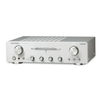
Marantz PM7200N1B User Manual

Marantz PM7200N1B
30 pages
To Next Page IconTo Next Page
Page #1 background imageLoading...
Page #1 background image
PM7200
20AW855010 MIT
First Issue 2002.07
Service
Manual
R
PM7200 /
N1B/N1G
Integrated Amplifier
PM7200
REMARK : This service manual shows only the differences between the model PM8000
/N1B /N1G and the model PM7200 /N1B/N1G.
All other information is described in the service manual of the model PM8000 (code
number: 3120 785 22011 and 276W855010). For the dispatch of the after-sales service
parts, refer to those service manuals with the first priority.
Therefore, please use this document with referring to the model PM8000 service manual
without fail.
POS. NO.
VERS.
COLOR
PART NO.
(
FOR EUR
)
DESCRIPTION
PART. NO.
(
MJI
)
200
/N1B 20AW248010
FRONT PANEL BLACK
20AW248010
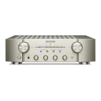
200 /N1G 20AW248020 FRONT PANEL GOLD 20AW248020
387
20AW851310
USER GUIDE
20AW851310
3120 201 60420
3120 201 60430
3120 205 20390
NOTE : "nsp" PART IS LISTED FOR REFERENCE ONLY, MARANTZ WILL NOT SUPPLY THESE PARTS.
The changed parts are listed below. Not listed parts are the same to the model PM8000.
www.electronicsrepair.net
Question and Answer IconNeed help?

Do you have a question about the Marantz PM7200N1B and is the answer not in the manual?

Marantz PM7200N1B Specifications

General IconGeneral
Input Sensitivity (High level)200 mV
Channels2
EthernetYes
Wi-FiYes
BluetoothYes
Headphone OutputYes
Speaker A/BYes
Phono InputYes
Digital InputsOptical, Coaxial
StreamingYes

Summary

1. Specifications

Key Performance Specifications

Details power output, impedance, and dynamic power ratings.

4. Block Diagram

Signal Flow and Source Selection

Illustrates signal routing through the source selector and amplifier stages.

Amplifier Stages Overview

Shows the signal path through volume, flat, tone, and power amplifier stages.

6. Schematic Diagram and Parts Location (Parts Side)

Function and Tape In/Out Circuit Schematics

Detailed schematics for the function input and tape input/output circuitry.

Main Circuit

Main Amplifier Output Stage and Speaker Protection

Schematic of the main amplifier output stage and speaker protection circuits.

Volume Control Circuit (PM7000)

Volume Control Circuit (PM8000)

7. Exploded View and Parts List

Exploded View Diagram

Visual representation of the amplifier's internal components and their assembly.

8. Idling Current and DC Offset Voltage Alignment

9. Electrical Parts List

Electrical Parts List Overview

Introduction and start of the detailed electrical parts list.

Related product manuals