I
Tunea
I tco
coHilEcTttIG coruPnilEilTs
Connect all
necessanT
audio/visual
componenls
to the
rear
panel
ol
the
unit,
using
RCA
phono
plugs.
See
the illustration
for
properly
completed
c0nneclions. When connecting ffCA
phono
plugs
be
sure
lhat L(left). R(right) markings
on
each component
are matched co.rectly.
connect
the
ground
wirqof the
turntable to the terminal
marked
GND on the.
rebeiver.
.
PHolto
tilliltc SELEET0B
The unit
has a built-ii MC head
amplifier,
you
can select the MM
(moving
magnet) or MC(mw-
ing
coil)
phono position"
lf
your
turntable
uses
an
MC
catuidge, set
ihe
selector
to the
MC
posi
tion. ll
an
MM
cartridge
is
used,
sel
the selector
to the
MM
position-
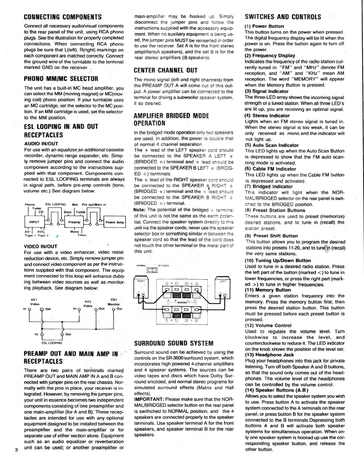
ESr. t0oPtilG
rn AllD ouT
RECEPTACTTS
AUDIO
IN/OUT
For
use
with
an equalizer,an
additional casseue
recorder,
dynamic
range
expander. elc.
Simp-
ly
remove
jumper
pins
and connect
ihe
audio
component
according to
the
instructions
sup-
plied
with that component.
Components
con-
nected to ESL LOOPING terminals are always
in signal
path,
be{ore
pre.amp
controls
(tone,
volume etc.) See
diagram below:
ESL L@PING
f,lid
Ra
aul/tlai.
i.
Tre&
Tape r
VIDEO INIOUT
For use
with a
video enhancer,
video noise
reduction device,
etc. Simply
renoveiumper
pin
and
cunnecivideo
component as
per
the
instruc-
tions
suppl,ed wath that
component. The
equip
ment connecled
to this loop
will
enhance dubb-
ing between
video sources
as well
as monitor-
ing
playback-
See diagram
below:
AV!
Vftleo
PREAMP
OUT AilD
MAIil AMP
IT
:
BEGEPTAGLES
There
are two
pairs
of terilinals marked
PREAMP
OUTand
MAIN AMP
lN A and B con-
nected with
jumper
pins
on
the reai
chassis.
Nor-
mally with the
pins
in
place, your
receiver is iru
tegrated.
Holvever, by remwirE
the
lumper
pins,
your
unit in essence
&comes
tn,o independent
components
consisting
of bne
preamplilier
and
one main-amplifier
(for
A and B).'These
recep
tacles are
intended lor
use
with
any
optional
equipment
designed to
be
installed
between
the
preamplilier
and
the
main-amplifier or for
separate
use ol
either section alone. Equipment
such
as
an audio
equalizer
or
reverberation
unit
can
be
used; or another
preamplilier
or
main-ampiifier may be
hooked
up.
Simply
disconnect the
jumper
pins
and
lollow
the
instructions
supptted
with
the
accessory
equip-
fient. When
no
auxiliary equipment
:s
being us-
ed, the
jumper
pins
MUST
be
reinserted in order
to use the
receiver.
Set
A is for
the front stereo
amplifierslA speakers), and
the
set B
is for
the
rear
stereo amplifiers
(B
speakersi.
CEITTEB CHAffiIET OUT
The mono
signal
(left
and right
channels)
from
the PREAMP OUT
A
will come out oi this out-
put.
A
povJer
amplifier
can be
connected to the
terminal lor driving a subwoofer
speaker system,
if
so
desired.
AflIPLIFIER
BBIDGED MODE
OPERATIO[I
ln the bridged
mode operation
onl!,
t!'rc speakers
are
used,
ln
addition,
the
power
is
double
that
of
normai 4 channel
separation.
The s lead
of the LEFT speaker
coro
shculd
b€
CONNECTEd tO ThE SPEAKER
,A
LEFT
=
(BRIDGED
e)
terminal and e leac
shculd be
connected
to the
SPEAKEF B LEFT : IBRIDG.
ED
c
)
tenninals.
The e lead
of
the R]GHT
speaker
ce.c sf'rcrid
be connected
to the
SPEAKER
A FtGHi :
(BFiIDGED
a
)
terminal and the .
1"."
=*"",d
bC
CONNCCIEd
tO thE SPEAKEB
B
RIGHT
=
(BBIDGED
=
)
lerminal.
Note:
The
potential
ol the
bridged
+
termiral
of this unii
is not the same as
the
earih
Fcie.-
tial. connecl
the speaker system
direclly ic l::;s
unit via the speaker
cords;
never
use the spsaker
selector
box
or something similar ln betlye€n
ihe
speaker cord sO lhat the
lead
of lhe cord dces
not
touch
the
other lerminal or the metal oan oi
this unit.
se$r!
_
3,'c6f
D
lL-l-lr
SUBBOUIIID SOUilD
SYSTEM
Surroirnd
sound can be
achieved
by using the
controls on
theSR-3600suribund
system,
which
incorporates
high
powered
4-channel
amplifiers
and
4
speaker systems.
The
sources can
be
video
tapes and.discs
which
have
Dolby Sur-
round
encded,
ard
normal
slereo
programs
for
simulated
surround effects
(Matrix
and
Hall
ellects).
IMPORTANT:
Pleise make
sure that the
NOFI-
MAUBRIDGED
selector
button on the
rear
panel
is swithched
to NOBMAL
position,
and
the 4
speakers
are connected
properly
to the
speaker
terminals. Use
Speaker termipal A
for
the
lront
speakers,
and
speaker
terminal
B
for the
rear
speakers.
swrTcHEs
Ait0
c0ilTn0ts
(1)
Power Button
This
button turns on the
power
when
pressed-
1-he
digital
frequency
display will
be
lit when
the
power
is
on. Press the button again to
tum
off
the
power.
(2)
Frequency Display
hdicates
the
trequency
o,
the
radio
station cur-
rently
tuned in.
"FM"
and
"MHz"
denote
FM
reception,
and
"AM"
and
"KHz"
mean AM
reception.
The word
"MEMORY"
will appear
when
the Memory Button is
pressed.
(3)
Signal lndcator
The
three.LED
array
shows
the
incoming
signal
strengith
ot a tuned station. When
all
three LED's
are lat
up,
you
are receiving
an
optimal signal.
(4)
Stereo lndicator
Lights
when
an
FM
stereo signal
is
tuned
in.
When
the stereo signal
rs
loo weak, it
can be
only
received
as
mono
and lhe
indicator
will
not
light up.
{5)
Auto
Scan
lrdicator
This
LED
lights
up when the Auto
Scan
Button
is
depressed
to show that the FM auto scan-
ning mode
is
activated.
(6)
Cable FM lndicator
This
LED lights
up
when
the
Cable
FM bulton
is
depressed
and acttvated.
{7)
Bridged
lndiqator
This
indicator
wil! light
when the
NOR-
il/AUBRIDGED
slector
cn the
rear
panel
is
srvit-
ched tc
the
BBIDGED
posilion.
i8l
Preset
Station Buttons
These
buttons
are used to
preset
(memorize)
Gesire{i
statio.rs, and
to tune in
(recall)
the
staiton
preset.
(91
Preset
Shift Bufton
This
bulton
allows
you
to
program
the
desired
stations into
presets
11-20,
ard
to
tuneh
(recall)
the very
same slations.
{10)
Tuning
Up/Down
Button
Used to tune in
a desired radio
slalion.
Press
the left
part
of
the
button
(marked
<
)
to tune in
lower
lrquencie$,
or
press
the
right
part
(mark-
ed
>)
to tune in higher
frequencies.
(11)
tlemory Button
Enters a
given
station lrequency into
the
memory.
Press the memory button
tirst,
then
press
the
desired
station button-
This bltton
must
be
pressed
before each
preset
button
is
pressed.
{12)
Votume
@ntrol
Used lo regulale the volume level. Turn
clockwise
to
increase the
level,
and
counterclockwise
to
reduce
it. The LED indicator
on
the knob shows the
position
of the
level
set.
(13)
Headphone
Jack
Plug
your
headphones into
this
jack
for
private
Iistening.
Tum
olf
bdh
SpeakerAard
B buttons,
so that the
sound
only comes
ojt of
the
head-
phones.
The
volume level
of the
headphones
can
be controlled
by
the volume
control.
(1'l)
Speaker
Buttons
(A.B)
Allouts
youto
sdectthespeakerslpem
you
wish
lo
use. Press
button
A to
activale
the speak€r
system
connected to
the
A
terminals
on
the
rear
panel,
or
press
button B
for
the speak€r system
connected
to the B terminals.Depressing
both
buttons A
and B will activate both speaker
systems lor
simultaneous
operation.
When on-
ly
one speaker
s].stem
is
hooked
up
use
tfte cor-
responding
speaker button, and
release the
other
button.
cnT
llonilor
6Od
av2
Video
 Loading...