EasyManua.ls Logo

Marantz SR5200 N1G User Manual

Marantz SR5200 N1G
52 pages
To Next Page IconTo Next Page
Page #1 background imageLoading...
Page #1 background image
AV Surround Receiver
SR5200 / SR6200
321W855010 MIT
3120 785 22800
First Issue 2001.12
Service
Manual
SR5200 /K2G, /N2G, /N2B, /U2B
/K1G, /N1G, /N1B, /U1B
R
SR5200 / SR6200
Please use this service manual with referring to the user guide ( D.F.U. ) without fail.
TABLE OF CONTENTS
1. TECHNICAL SPECIFICATIONS .................................................................................. 1
2. WIRING DIAGRAM ...................................................................................................... 5
3. BLOCK DIAGRAM ........................................................................................................ 7
4. SCHEMATIC DIAGRAM ............................................................................................... 9
5. PARTS LOCATION .................................................................................................... 27
6. IC DATA ..................................................................................................................... 40
7. EXPLODED VIEW AND PARTS LIST ........................................................................ 43
8. ALIGNMENT PROCEDURES .................................................................................... 49
9. ELECTRICAL PARTS LIST ........................................................................................ 52
AV SURROUND RECEIVER SR6200
UP
SURROUND
VOLUME
DOWN
MEMORY
TUNING/PRESET
MODE
F/P
CLEAR
NIGHT
ATT
DISPLAY OFF
SLEEP
S-DIRECT
DIMMER
MUTE
A/D7CH INPUT
POWER ON/OFF
PHONES
STANDBY
AUX INPUT
S-VIDEO VIDEO L AUDIO R
A
SLEEP
MUTE
ANALOG
DIGITAL
MLP PCM
RF AUTO LOCK CIRCLE SURROUND EX MPEG DIRECT MEMORY PRESET SW LFE
SRSCSLRTTAPTYAUTOTUNEDDSP SOUNDVIRTUAL
1 2 3 4 5 6
DIGITALDTS
THX
RCLCTTPEONRDSSTEREOTAPE 2 MON
PRO LOGIC
VIDEO SET
B
DOLBY
DSS/VCR2 AUX
VCR1
DVD
TV CD
CDR/MD
TAPE
TUNER
AV SURROUND RECEIVER SR5200
UP
SURROUND
VOLUME
DOWN
MEMORY
TUNING/PRESET
MODE
F/P
CLEAR
SLEEP
S-DIRECT
DIMMER
MUTE
A/D7CH INPUT
POWER ON/STANDBY
PHONES
STANDBY
AUX INPUT
S-VIDEO VIDEO L AUDIO R
A
SLEEP
MUTE
ANALOG
DIGITAL
MLP PCM
RF AUTO LOCK CIRCLE SURROUND EX MPEG DIRECT MEMORY PRESET SW LFE
SRSCSLRTTAPTYAUTOTUNEDDSP SOUNDVIRTUAL
1 2 3 4 5 6
DIGITALDTS
THX
RCLCTTPEONRDSSTEREOTAPE 2 MON
PRO LOGIC
VIDEO SET
B
DOLBY
DSS/VCR2 AUX
VCR1
DVD
TV CD
CDR/MD
TAPE
TUNER
NIGHT
ATT
DISPLAY OFF
SR5200
SR6200
SR6200 /K2G, /N2G, /N2B, /U2B
/K1G, /N1G, /N1B, /U1B
Question and Answer IconNeed help?

Do you have a question about the Marantz SR5200 N1G and is the answer not in the manual?

Marantz SR5200 N1G Specifications

General IconGeneral
Channels6.1
Frequency Response10 Hz-100 kHz (+1, -3 dB)
Total Harmonic Distortion0.08%
TypeAV Receiver
Digital audio inputCoaxial, Optical
Surround Sound FormatsDolby Digital, DTS, Dolby Pro Logic II
Signal-to-Noise Ratio105 dB
Inputs6 x audio
Input Sensitivity200mV
Input Impedance47k ohms
Video SwitchingComposite, S-Video

Summary

Marantz Design and Service

Shock, Fire Hazard Service Test

Safety test procedure for units after servicing to prevent electrical hazards.

Technical Specifications

SR5200 Specifications

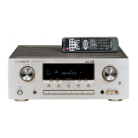
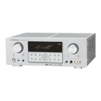
Detailed technical specifications for the Marantz SR5200 AV receiver.

SR6200 Specifications

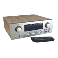
Detailed technical specifications for the Marantz SR6200 AV receiver.

Wiring Diagram

Internal Wiring Diagram

Diagram showing the electrical connections between internal components and boards.

Block Diagram

SR5200/SR6200 Block Diagram

High-level overview of the signal flow and main functional blocks of the receiver.

Schematic Diagram

Main B'D Schematic

Detailed circuit diagram for the Main circuit board.

DSP B'D Schematic

Detailed circuit diagram for the Digital Signal Processing board.

Schematic Diagram Safety Precautions

Important safety notes related to schematic diagram interpretation and handling.

Parts Location

Main B.D Parts Location

Visual guide showing the placement of components on the Main circuit board.

Exploded View and Parts List

SR5200 Exploded View and Parts List

Visual breakdown of the SR5200 unit with a list of all parts.

Alignment Procedures

Tuner Alignment Procedures

Steps and equipment required for aligning the Tuner section.

AM(MW) Alignment

Procedure for aligning the AM/MW frequency bands.

FM Alignment

Procedures for aligning the FM tuner section, including detection and separation.

Electrical Parts List - General Components and Safety

Fuse and Safety Notes

Information on fuses and critical safety warnings for parts.

Electrical Parts List - Volume & Speaker Boards

Electrical Parts List - Volume & Speaker Components

Electrical Parts List - Front Board Components

Electrical Parts List - Input1 Board Components

Electrical Parts List - Input2 Board Components

Electrical Parts List - DSP & Main Board Components

Electrical Parts List - DSP Resistors

Electrical Parts List - DSP Components

Electrical Parts List - S-Video Board Components

Electrical Parts List - Amp Semiconductors

Electrical Parts List - Power Board Capacitors

Electrical Parts List - Power & STBY LED Board Components

Related product manuals