8
3. POWER AMPLIFIER ADJUSTMENT
Idling Current Alignment
1. Each of the measurement points are provided with the
two test points. Set a digital Voltage meter to DC voltage
input, connect the meter to the test points at both con-
tact points.
2. After the setup above, turn on the main switch.
3. Adjust variable resistors (VR41, VR42…VR71) accord-
ing to the digital voltmeter readings. The target setting
value is the following table for each channel.
Settings: Master Volume — Minimum
Speaker out — No Load
Top lid — OPEN
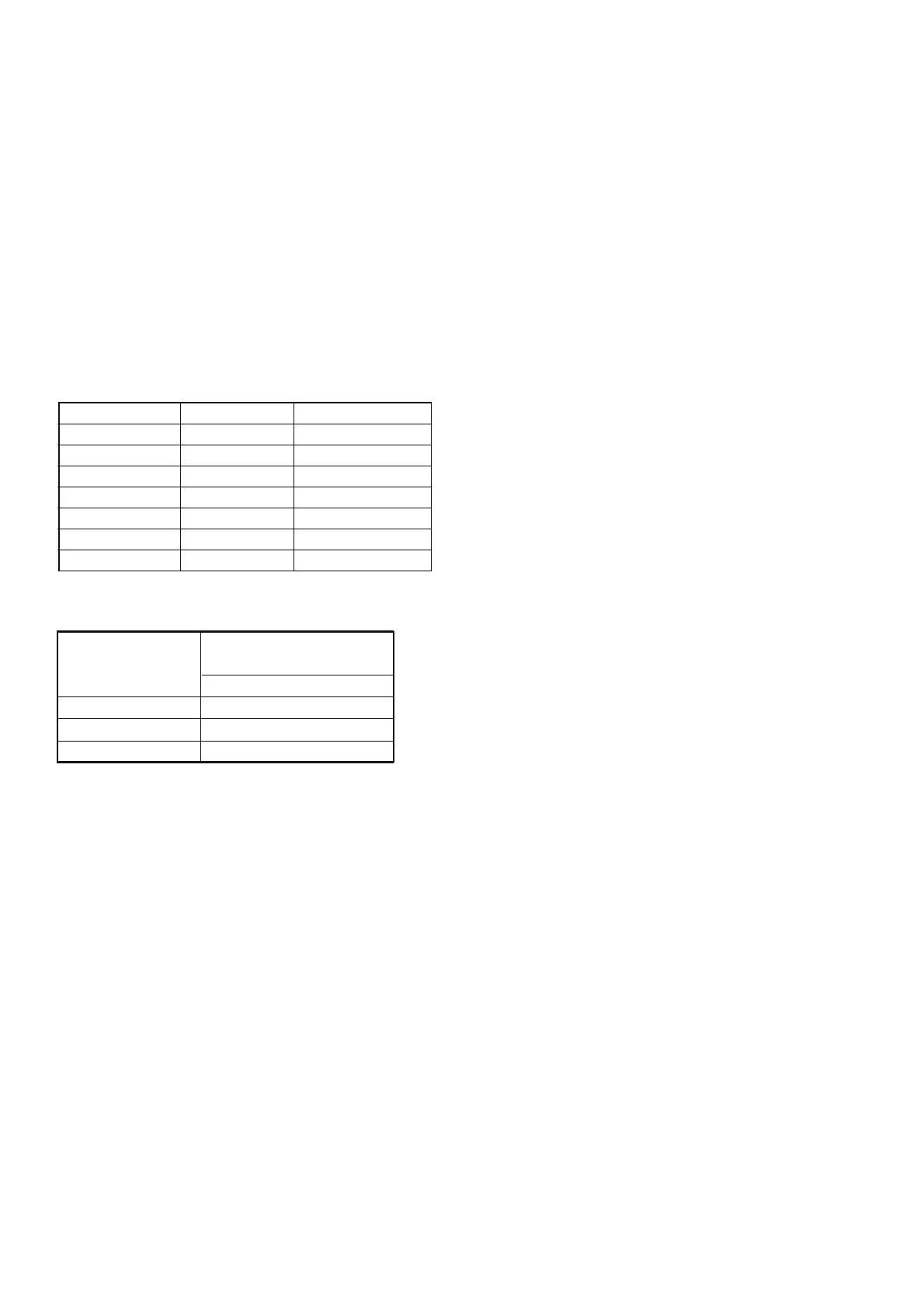
Channel Alignment Point Measurement Point
Front L VR41 CN41
Center VR61 CN61
Front R VR51 CN51
Surround L VR42 CN42
Surround R VR52 CN52
Surround Back L VR62 CN62
Surround Back R VR71 CN71
Time Table of Idling Current Rise
After Turning ON
Ambient temperature
20 to 30 degrees centigrade
Measurement Voltage
10 min. 2.4 mV ± 0.3 mV
20 min. 2.4 mV ± 0.3 mV
30 min. 2.4 mV ± 0.3 mV