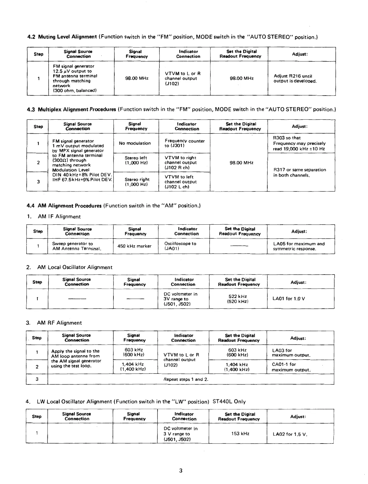
4.2
Muting Level Alignment (Function switch
in
the
"FM"
position, MODE switch in the "AUTO
STEREO"
position.)
Step
Signal Source Signal
lndicator
Set
the
Digital
Adjust:
Connection
Frequency
Connection
Readout
Frequency
FM signal generator
12.5~JV
output
to
VTVM
to
Lor
R
1
FM
antenna
terminal
98.00
MHz
channel
output
98
.
00
MHz
Adjust
R216
until
through
matching
(J102)
output
is
developed.
network
(300
ohm
, balanced)
4.3
Multiplex Alignment Procedures (Function switch
in
the
"FM"
position,
MODE
switch
in
the
"AUTO
STEREO"
position.)
Step
Signal Source Signal
lndicator
Connection
Frequency
Connection
FM
signal generator
F requency
counter
1
1
mV
output
modulated
No
modulation
to
(J301 l
by
MPX
signal generator
to
FM antenna
terminal
Stereo
left
VTVM
to
right
(30011)
through
2
matching
network
(1,000
Hz)
channel
output
Modulation
Leve!
(J102 R ch)
OIN
40
kHz+8
%
Pilot
OEV
.
VTVM
to
left
3
IHF
67.
5kHz+9
%
Pilot
OEV
. Stereo
right
channel
output
(1
,
000
Hz)
(J102
Lch)
4.4
AM
Alignment Procedures (Function switch
in
the
"AM"
position.)
1.
AM
1 F Alignment
Step
Signal Source Signal
lndicator
Connection
Frequency
Connection
1
Sweep gener
ator
to
450
kHz
marker
Oscilloscope
to
AM
Antenna
Terminal.
(JA01)
2.
AM
Local Oscillator Alignment
Step
Signal Source Signal
lndicator
Connection
Frequency
Connection
OC
voltmeter
in
1
---
---
3V
range
to
(J501,
J502)
3.
AM
RF
Alignment
Step
Signal Source Signal
lndicator
Connection
Frequency
Connection
1
Apply
the
signal
to
the
603kHz
AM
loop
antenna
from
(600kHz)
VTVM
to
Lor
R
the
AM
signal generator
channel
output
2
using
the
test
loop
.
1,404
kHz
(J102)
(1
,
400
kHz)
3 Repeat steps 1 and 2.
Set
the
Digital
Readout
Frequency
98
.
00
MHz
Set
the
Digital
Readout Frequency
- - -
Set
the
Digital
Readout Frequency
522kHz
(520kHz)
Set
the
Digital
Readout Frequency
603kHz
(600kHz)
1.404
kHz
(1,400
kHz)
4.
LW
Local Oscillator Alignment (Function switch in
the
"LW" position) ST440L Only
Step
Signal Source
Signal
lndicator
Set
the
Digital
Connection
Frequency
Connection
Readout Frequency
OC
voltme
ter in
1
3 V range
to
153kHz
(J501,
J502)
3
Ad
just
:
R303
so
that
Frequency
may
precisely
read
19,000
kHz
±
10
Hz
R317
or
same separati
on
in
both
channels.
Ad
just
:
LAOS
for
maximum
and
symmetric
response.
Ad
just
:
LA01
for
1.0
V
Ad
just:
LA03
for
max
i
mum
ou
t
put
.
CA01-1
for
maximum
output;
Ad
just:
LA02
for
1.5
V .