INSTALLING
THE
GA4S
Llh'E
If a lzft-hand installation is desired, knock out the plug
in
the fueplace case on the left-hand side. Proceed as for
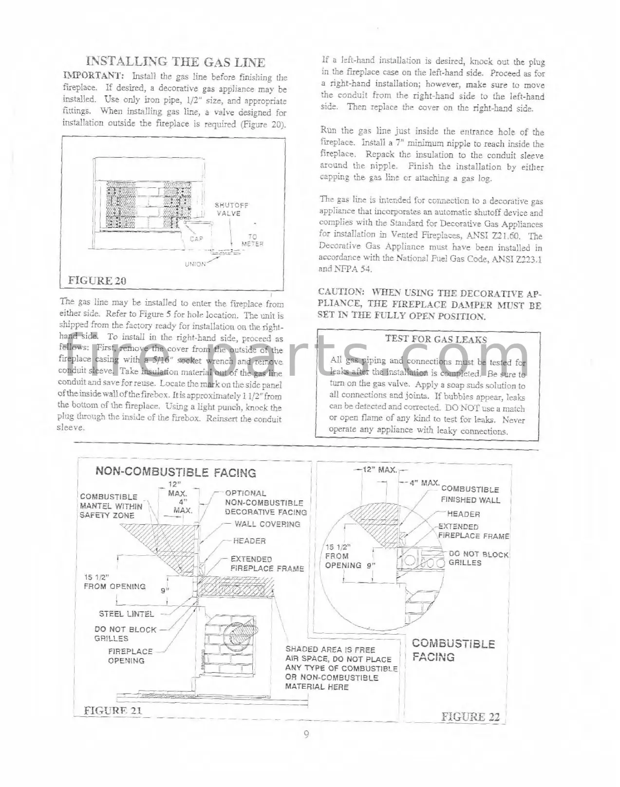
14IF'ORTANT:
Install the gas line before
fmisi;i=_e
ff~e
a right-hand installation; however, make sure to move
fireplace.
If
desked, a decorative gas appliance may be
the conduit from the right-hand side to the left-hand
installed. Use only
iron pipe,
112"
size, and appropriate
sidc.
%en replace the cover on the right-hand Side
firtings. When installing gas line, a valve designed for
installation
cutside the fireplace is required (Figure
203.
Run the gas line just inside the entrance holt of the
c
!
mep1ace. Install a
7"
mir2mum nipple to reach inside the
fireplace. Repack the insulation
to
the conduit slcve
/
*--------;
around the nipple. Finish the installation by either
capping
:he
?as
lint
or
at%chhp
a
gas
log.
The
gas
line is intended fcr cof'ulection to
a
decorative gas
appliance that incorporates
an
automatic shutoff device and
coinpli~s with the Standard for Decorati\,c Gas App!ianc%
far
instal!ation
in
Vented Fueplaccs,
kYS1
221.60.
P.e
Decorative Gas Appliance must
havs
been installed
in
accordance with the Xational File! Gas
Code,
.WSI
2223.1
and
NFPA
54.
(
FIGURE
20
CAC'TIO?':
\%TIEN
USlYG
TEE
DECORATn'E
AP-
The gas line
may
be installed to enter the fireplace from
PLIAXCE,
THE FIREPLACE DAXPER
MUST
BE
either side. Refzr to
Figure
5
for hole location. Rze unit
is
SET
IS
TEE
RjLLY
OPEN
POSITIOX.
shipped from
he
Facton. ready for insta1:alion on therigh!.
,
hand side.
To install in
the
right-hand side, proceed as
1
TEST
FOX
GAS
LEAKS
follows: First, remove the cover from the ouejide of t\e
fueplace casing wit+ a
5/16"
socket wench and iernovc
411 gas piping and connections must be tested for
coilduit s!eeve. Take Lu~ladoil ma:erinl out of t5e gas
he
1
ieak
ake: the instaltation is coinpieird. Re sure to
.
-.
-
-
-
-
-
-
...
-
-
-
-
-
.-
--
-
-
-
-
_
I
NON-COMBUSTIBLE
FACING
I
-12"
!
I
12"
-
-7
--
4"
MAX.
-
I
.-OPTIONAL
I
i
I
/
-
COMBUST~BLE
i
COMBUSTIBLE
,
MAX.
4"
,i
NON-COMBUSTIBLE
i
'
FiNlSHEC WALL
MANTEL
':I
!
MAX.
,
;
DECORATIVE FACLNG
,
I
SAFETY ZONE
.,
'
--
,-
WALL COVEDING
,
,
,
IREPLACE FRAME:
I
-
EXTENDED
'
15
?!2"
FROM OPENING
I
I
GR!LLES
-
-
-
/'
AREA
$S
FREE
CCV8BUSiiBlE
FIREPLACE
-'
--=s.
AIR
SPACE,
DO
NOT
PLACE
I
FACING
OPENING
!
e
<----~---,
",
1,
,
8
I
:
ANY TYPE OF COMBUSTIBLE
)
.--;2;
2---
-.
I
I
OR NON-COMBUSTIBLE
!
MATERIAL
HERE
,
-.*---
-
--a
!
1
-
I
--
_
FIGURF,
21
--
--
~-
-~
-
-
..
-
-
-
-
.
.
-
-
-
-
-
-
.
--
-
-.
.
FIGUXE
22
condui~ and save for reuse. Socate
t!!c
mnrk
on the side panel
offieinsidewall ofthefirebcx. Itisapprorimatrly I1!2"from
the hottorn of
the
fireplace. Usiqg a light punch, knock
the
plug
t!uough
the
iriside
of
the
hebox. Reinsee the conduit
sleeve.
turn on the gas valve. Apply
a
soap suds solution to
all connrctiom and
joink.
I:
b~tbbles appear,
laah
can
be detcc~ed and corectsd.
DO
KOT
use
a
ma:cti
or open flame of
any
in
tcst for leak. Never
operate any appliance with leaky
comectiors.
f i r e - p a r t s . c o m