hi
i-i'
<:
Sail
ii;e
t:..imblz
(TI.
ED)
in!-
$?.ace
+~,-~ii:?
the cciling
rnzking
sure the tliimhle :ene:;zres the
:sc:'
i
openin2.
Re thimble must extend complete.ly
s!l~-cs:l
I
the ceiling or roof cavity ra (he ourtmost plane
ni
rhe
1
,
root
NOTE:
Thimble extensions
m-82)
:.re
a:
ii!-
i
:>
*.
able from your hlarzo neaier iar constmciians in
u-hich
I
I
i
I
rhc
distance
between
the octsise
c;f
i!le
~33f
2x2
:?c
i
,,
,-.,
,
inside
of
the cc,i:inz exceeris
13".
TIP
thjmbje pmvides
1
,'
'\,.
for ze;o clearance to combustihies
and
mr!st
be
uue
et
I
I-
\
\
,
I,
the ceilin&oof in manufactured homes with
:la:li.i?-
i
,/
i
,,~
wail chimney (Fizure
12).
1
i
\
/'
.
-
.~. .
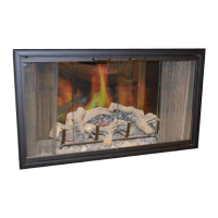
hOTE:
Tor cahedral or o;i?n
hea-
r?i!i?ys,
a .n!r;?!-
i
I
(FTC-SC.1
is
zviilsbls
ta
elizicatz
;iie
neeti
far
a
hrnder
1
I
F!C;T?RE
E1
i
i
3°K
PlPE
7
I
;"%!i:?:EY
L,
i
I
I
i
j
j
,
10
--
i
i
---
?3'
--
,"'
MtM.
I
,-~
-
9
,
I
1
14'
MIN.
,
--
36'
-a.
7-7
:
4
1
c;
'
-:
.--
<.'~
~~..
?;;
I
NCTE.
ESULAR
THIHSLE
CAN
BE
USED
li
A HcA%3
1:
WST%UEO
47
W3.S
FfGuRE
15
i
FIGURE
13
P0'h.T.
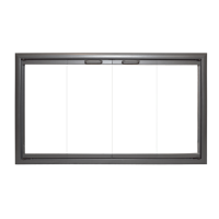
Extend
the
chimney
by adding sections of double-wall
/cATHEDRALCEIL~~GINST.ALLATION
I
ripe, as shown on Page
5,
until the pipe, including
chimrey lop,
is
a
minimum
of
35"
above
thc.
highest point
STEP
JL
ljncover the pipe and add sections until the
top
of
!he
roof clltor~t $pre
1%.
joint exten& a minimum of
14"
above :he Fjghes: poin:
of
!he
roof cutout (Figwe
13).
Position the fleshinF
owz
NOTE:
You may wish to
calk
s=an notches on
all
joints
the chime:: 2nd flal on *e roof. Mark
an
outline of the
above
the
flashing and
pzinr
all
exposzd
of
the
fleshing on the roof and remove the flashing. Remove
all
c!im~.y with galvanized primer paint.
A
coat of paint to
nails within the outlined mea
(Figure
14).
Place
flashing
match the house may then he applied.
%.to position on unshingled roof.
Hold in position
by
nailia shin~lm in
place
over the flashing
edges.
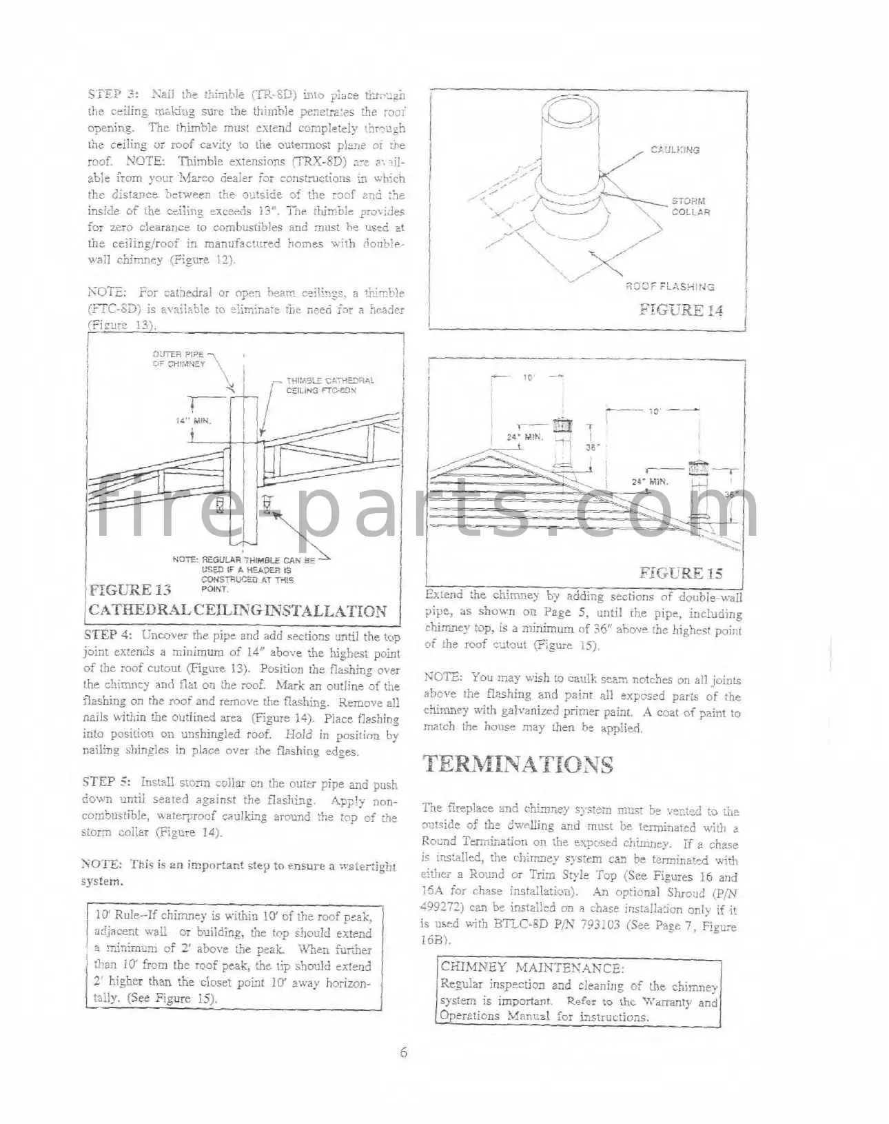
STEP
I:
Ins?a!l stom coiizr on the o!:te; pipe a;,d push
TERMINATIONS
down until ieated against the flashing.
~pply nun-
Kle 5rsplace snd chimney
s:,.~:-%
mmdst
bn
xn:&
to
bte
comh:lstible, urate~roof saulking awmd the top
cf
th-
o?l!side of :ht Liue1::iing md
nust
be teminated
with
a
storm collar
(Figure
14).
Rod Temina6on on !he e-,~c:scd shiiiu~ey,
if
a
chve
is
mszlled,
the
chimney system can be teminated u,iih
SOTE:
This
is
an important step
to
ensure
a
nster:ight
eithe;
3
Round or Trim Sy!e Top (See Figures
I6
and
system.
:5A
for chase insta:Iation).
.LT
opiionai S>~o:ld
(pfl
499279
can bz i~staiied on
a
chase insiaIh:ion only if it
I
10'
Rule--If chimney is within
10'
of
the roof peak,
adjacent wall
M
building, the top should extend
I
i
iin;rn;m of
5
above
ih
?mi.
%<,en
br;>er
is used with
RTLC-SD
Piy
793103
!See Page
7,
FIeure
i63i.
:!?an
10'
from the roof peak,
the
tip should extend
2'
higher than the closet point
10'
away
horizon-
Re~lar
inspection and cleaning of
the
c.hinne?
tiily. (See Figure
15).
i
system is impsrfant.
Rofer
to
thc
Warranty and
5
f i r e - p a r t s . c o m