MTEC~
e
lo
55
"001
-..
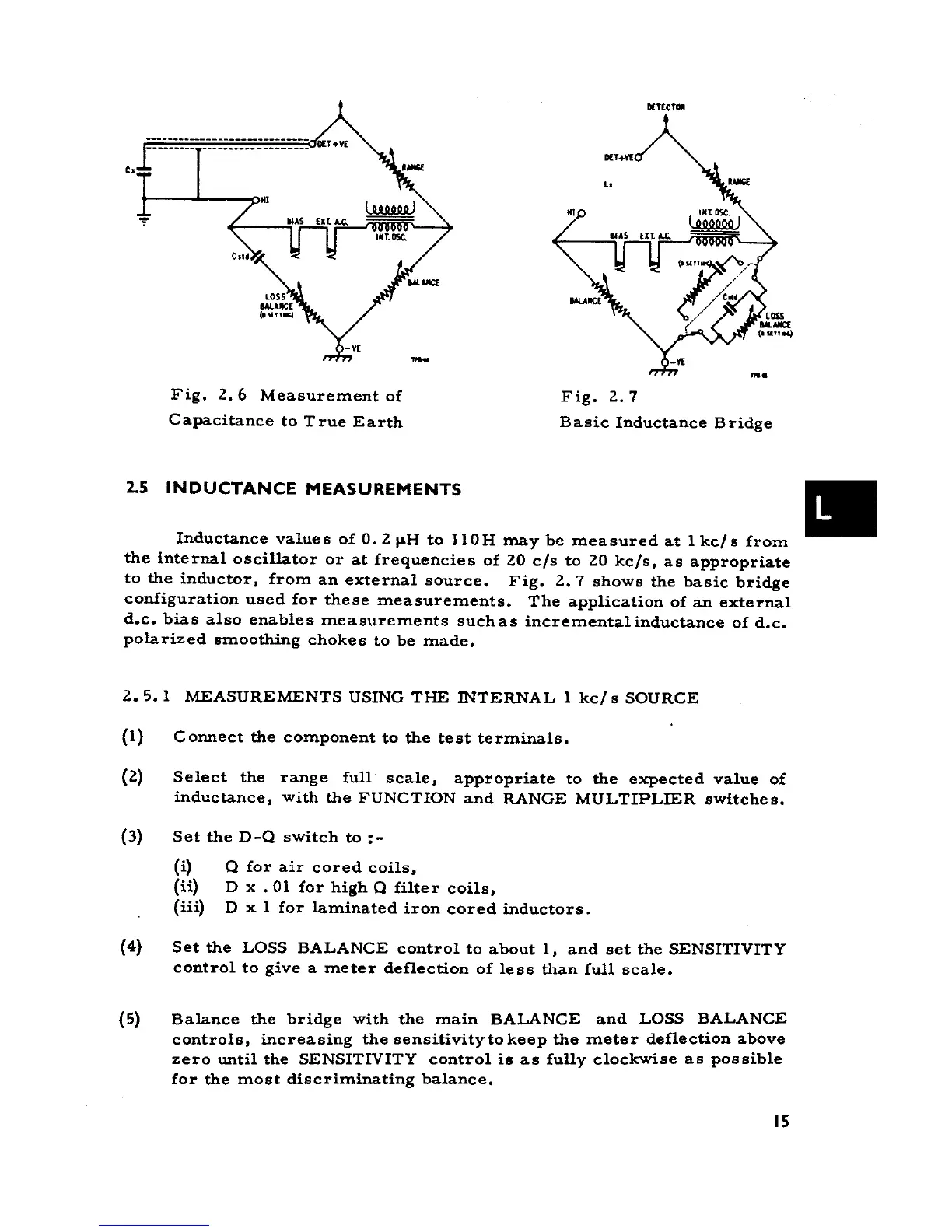
Fig. 2.6 Measurement of Fig. 2.7
Capacitance to True Earth Basic Inductance Bridge
2.S INDUCTANCE MEASUREMENTS .
Inductance value s of O. 2 I1H to 110 H ma y be mea sured at l kc/ s from
the internaI oscillator or at frequencies of 20 c/s to 20 kc/s, as appropriate
to the inductor, from an external source. Fig. 2.7 shows the basic bridge
configuration used far these measurements. The application of an external
d.c. bias al so enables measurements suchas incrementalinductance of d.c.
polarized smoothing chokes to be made.
2.5. l MEASUREMENTS USING THE INTERNAL l kc/ s SOURCE
(l) Connect the component to the test terminals.
(2) Select the range full scale, appropriate to the expected value of
inductance, with the FUNCTION and RANGE MULTIPLIER switches.
(3) Set the D-Q switch to :-
(i) Q far air cored coils,
(ii) D x .01 far high Q filter coils,
(iii) D x l far laminated iron cored inductors.
(4) Set the LOSS BALANCE contrai to about l, and set the SENSITIVITY
contrai to give a meter deflection of less than full scale.
(5) Balance the bridge with the main BALANCE and LOSS BALANCE
controls, increasing the sensitivitytokeep the meter deflection above
zero until the SENSITIVITY contrai is as fully clockwise as possible
far the most discriminating balance.
15