2.2 BATTERY CHECK
Since the bridge is battery powered its measurement sensitivity will
be dependent on battery voltage. This may be monitored by connecting a
voltmeteror anammeter between the DET+VE and -VE (chassis) terminals
with the bridge set to the lO M.'"2, R INT D. C. range. The voltage measured
should be at least 6 V or the current at least 40 mA; if not, the battery
should be replaced, far details see Section 4. l.
NOTE: In arder to preserve the battery the instrument should be
switched OFF after each measurement. When an external
bias is being used the precautions given in the appropriate
Operation section mustbe observed before altering the positions
of the FUNCTION and RANGE MULTIPLIER switches.
2.3 CONNECTIONS
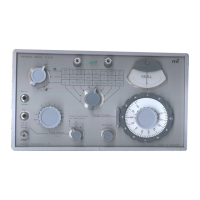
Components to be measured are connected across the two large term-
inals marked HI and DET + VE. The connecting leads should be kept as
short as possible in arder to avoid introducing stray capacitance and mains
hum pick up which will obscure the balance indication.
When measuring large items or componente it is important to avoid
the introduction of external interference signals via the DET +YE terminaI
or else a poor or false balance will be obtained. li the component has an
isolated screen it is probably best to connect this to the -VE (chassis)
terminaI; but in the event of this screen having too large a capacity (say
aver 200 pF) to the contents on test, it may be alternatively connected to
the HI terminaI. The screen in this case must be well isolated or spaced
from the bridge case to avoid re-introducing the stray capacity.
Two P40 jack plugs are provided with the Bridge far the connection
of external a. c. and d. c. supplies. An alternative a. f. energizing source
should normally be connected to a jack plug inserted into the EXT A. C.
socket. The d. c. supply far a polarizing bias should be similarly c onne ct-
ed to the BIAS socket.
For some measurements an alternative detector may be connected
between the DET +VE and -VE (chassis) terminals in arder to obtain a
more sensitive balance indication. Full details of these connections are
given in the section appropriate to the desired type of measurement.
9