2..1.2. READING THE RESULT
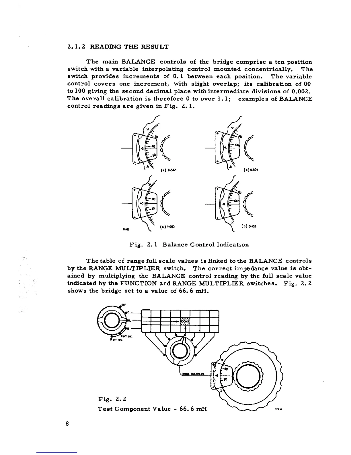
The main BALANCE controls of the bridge comprise a ten position
switch with a variable interpoIating contraI mounted concentrically. The
switch provides increments of O. l between each position. The variable
contraI covers one incremento with slight overIap; its calibration of 00
to 100 giving the second decimaI piace withintermediate divisions of 0.002..
The overall calibration is therefore O to aver 1.1; examples of BALANCE
contraI readings are given in Fig. 2.. l.
( (
c.}o.s.. (o) 00604
QJ( (
(c) ,- (o) 0-.0.
Fig. 2.. l BaIance ContraI Indication
The table of range full scale values is linked to the BALANCE controls
by the RANGE MULTIPLIER switch. The correct impedance value is obt-
ained by multiplying the BALANCE contraI reading by the fun scale value
indicated by the FUNCTION and RANGE MULTIPLIER switches. Fig. 2.2
shows the bridge set to a value of 66.6 mH.
...
~
""K
Fig. 2.2
Test Component Value - 66.6 mH
8