For low frequency measurements, such as 50 c/s, an ordinary mains
tranaformer may be used to supply the bridge, but it is best to have the
secondary screened from the primary and for the winding capacity to be
lesa than 100 pF. Connect the screen to the -VE (chassis) terminaI.
When using a high voltage level, overload of the first detector stage
may obscure initial balance indication. The sensitivity of the detector ma y
be controlied under these circwnstances bymeans of a variable resistor or,
say, lO K1 connected between the DET +VE and -VE (chassis) terminale.
If external bias is alBo being applied, block the d. c. by connecting a
capacitor of about 4 fAF in series with the variable resistor.
Maximwn A. C. Voltage
The maximwn permissible voltage that may be applied to the bridge is
governed by the current rating of the bridge resistors. It is very much
dependent upon the range in use and whether the test component is C, L, or
R. A Baie maximum e.m.f. for ali ranges is 35 V r.m.s. open circuit from
a 600 a source. This limita the maximwn power into the bridge and test
component to :}W. This voltage is more than adequate for ali normal
measurements, the e. m. f. from the internaI oscillator being 170 mV on
the six lowest impedance ranges and 1.5 V on the top two.
A. C. Voltage across Inductors
With the maximwn y,oltage limitations given in the previous paragraph
it is possible to have 3 to 4 Vat l kc/s across an inductor on test on the top
three ranges (values from l to 110 H). With lower value inductors and
lower frequencies the permissible inductor voltage isproportionately lesso
The actual voltage across the inductor on test at balance may be measured
with a high impedance valve voltmeter connected between the HI and
-VE (chassis) terminale.
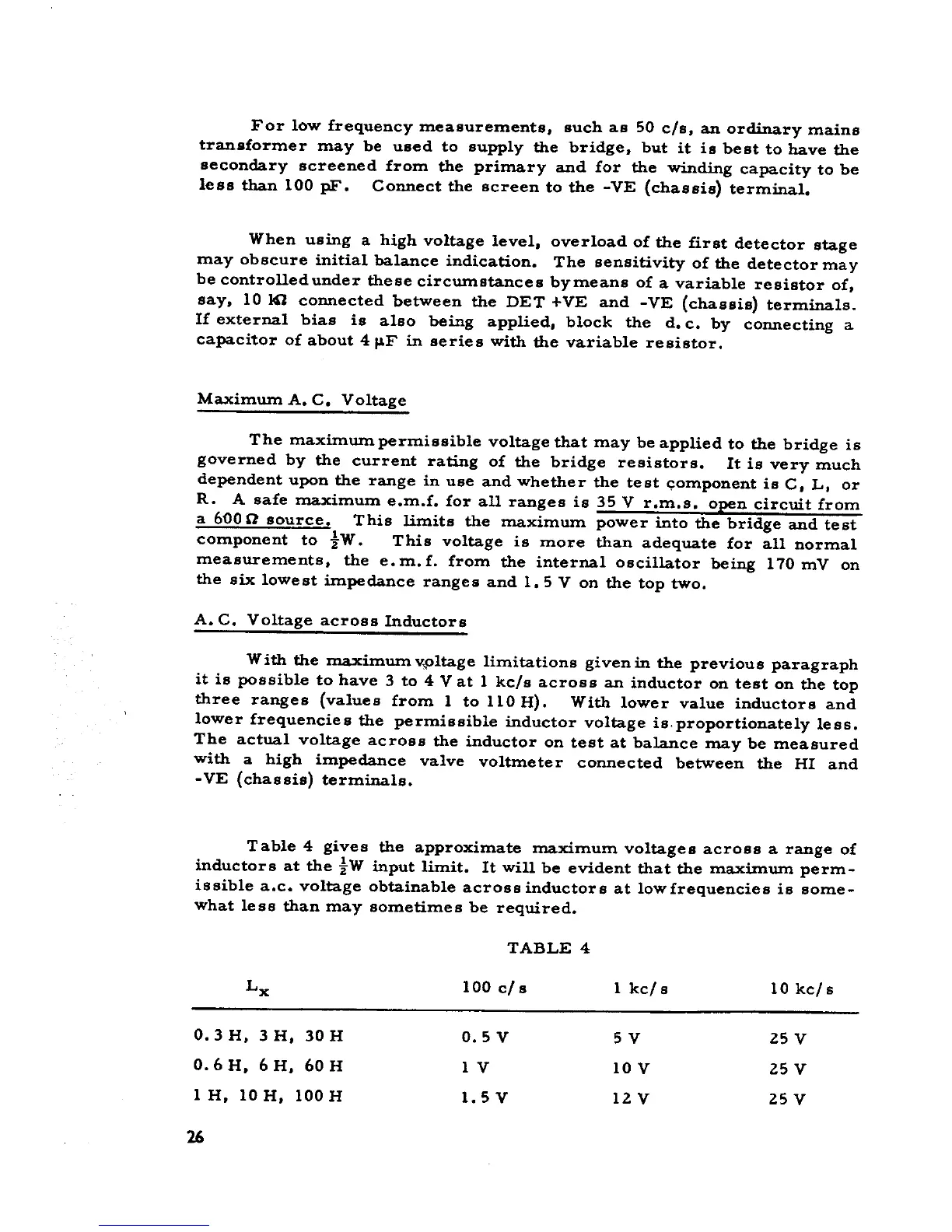
Table 4 gives the approximate maximum voltages across a range of
inductors at the :}W input limito It wili be evident that the maximum perm-
issible a.c. voltage obtainable across inductors at lowfrequencies is some-
what lesa than may sometimes be required.
TABLE 4
Lx 100 c/s l kc/s lO kc/s
0.3 H, 3 H, 30 H 0.5 V 5 V 25 V
0.6 H, 6 H, 60 H 1 V lO V 25 V
l H, lO H, 100 H 1.5 V 12 V 25 V
26