41
Supply cable to the pump is furnished with plug for connecting to the socket of
electric circuit 230V / 50Hz. This electric circuit must meet particular standard
(CSN33 2000) and must be furnished with current circuit breaker with tripping
current 30 mA. The pump is not furnished with controller of operation. We recom-
mend to connect it through the device enabling switching the pump on and o
(switching socket for instance).
Installation
Due to higher sealing capacity we recommend to use teon tape. Apply suitable
grease on the sealing surface before assembly.
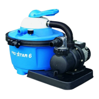
1) Placement of pump on the base
• Place the pump on the base as it is shown in the introductory picture
• Insert the two supplied stainless steel screws with washer in the hole bored in the
base and using nuts attach the pump to the base - see g. 2.1
• After it put the ltration vessel in two holes on the base in a way so that the lock
of lid position, g. 2.2, is aimed at the pump.
2) Preparation of the pump
• Unscrew the nut of suction socket, insert the sealing in the pump suction chamber.
Then put the clear suction chamber on and screw it tightly using the nut. Into the
hole in the clear suction chamber put O-ring and hose stud (see g.2.3). Before
screwing the hose stud on, we recommend to wrap its thread in the teon tape and
tighten only by hand to prevent possible damage of clear suction chamber.
• Insert O-ring in the discharge socket and screw the exible hose on, by hand and
tightly
• The drain screw of the pump must be rmly tightened.
3) Preparation of the vessel
• Disconnect installed buckle from the vessel
• Insert the partition in the vessel by slipping it on side guides, the partition upper
edge must match with vessel upper edge (see g. 2.4 and 3).
1) View of ltration vessel without lid
2) Filtration vessel bottom screen
3) Chamber with sand ll
4) Partition (clean water /chamber with sand ll)
5) Chamber for clean water
6) Water inlet from chamber with sand ll
7) Position lock of the lid ( the nose on ltration vessel lid must t here).
4) Filling the vessel with sand
WARNING!: he level of sand may not go beyond the upper horizontal reinforce-
ment of the interior partition. Maximum volume of sand ll must not be bigger
than 17 kg.
• Before putting the sand ll the ltration vessel must be lled with water to 20-
30cm height in order to prevent possible damage of the vessel and bottom glass.
EN