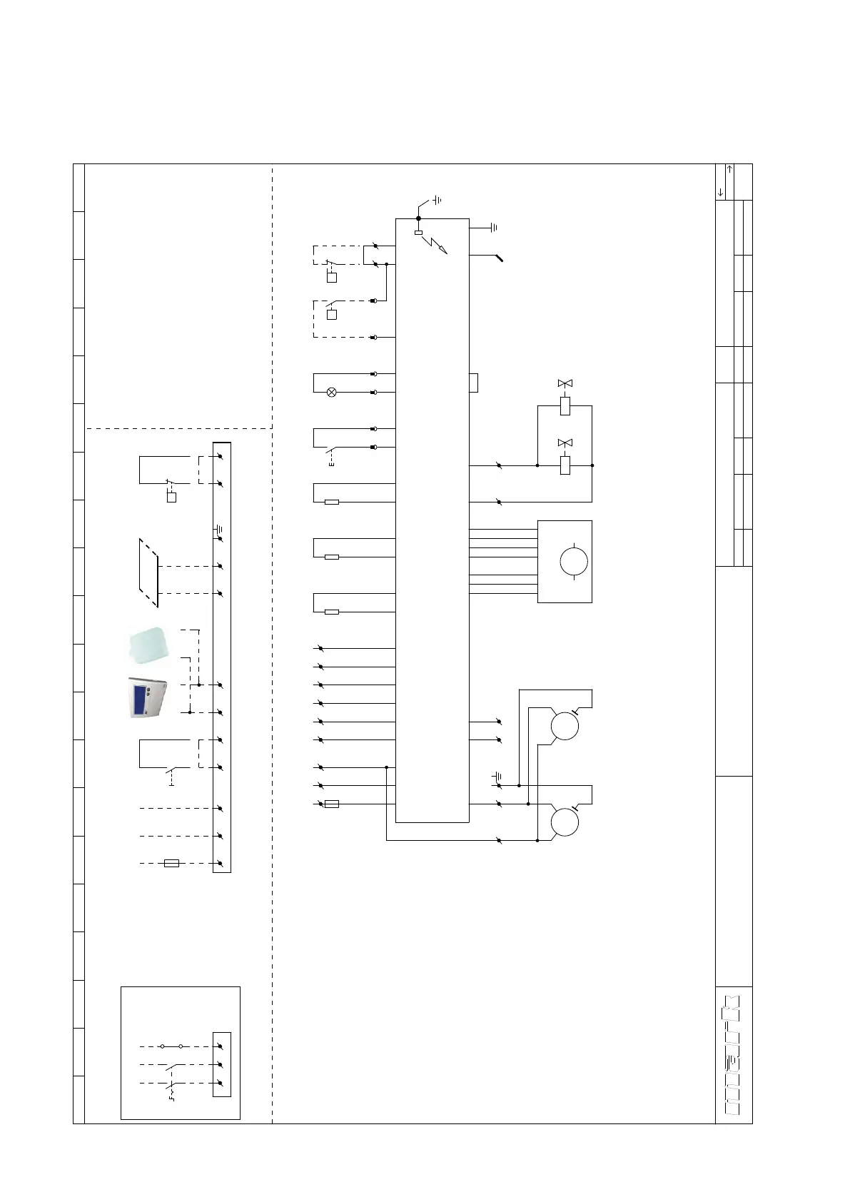
8.0 Schéma électrique GS+ 15 - 80
Pour GC+: voir l’intérieur de l’appareil.
56
1 2 3 4 5 6 7 8 9 10 11 12 13 14 15 16 17 18 19 20
GS+ 15-80
Get.
Gec.
Schema electrique
J.W.
TvD
Date
Norm
28-1-2022
Schéma
d'electrique
Groupe
Art.nr.
WLV Type
Version
WLV-012200-FR
GS+
1.1
1
c l i m a t i s a t i o n
R
Argus 864MN
Ts = 5sec
Tp = 30sec
Alimentation
Sonde de température digital (option)
Réarmement á distance
Interrupteur marche/arret (facultative)
Thermostat d'ambiance digital
Ventilateur de chauffage
Barre d'ionisation
Témoin défaut
Vanne gaz
Fusible
-
-
-
-
-
-
-
-
-
TT3
S2
S1
RT
VLV
IS
H1
GV1,GV2
F1,F2
1˜ 230V / 50Hz
L'interrupteur de proximitéWS -
TT1
TT2
-
-
Sonde de température de proximité
Sonde de température système / maximal
PE
Pressostat de filtre (si nécessaire)-PF
Raccordement externe
RT TT3
Maximum 8
appareils
BUS
facultative
Moteur ventilateur 1VM1 -
Moteur ventilateur 2 (GS+80)-VM2
Pour aérothermes avec 2 ventilateurs
Sonde d'eau de condensation (facultative)-W
facultativefacultative
(GS+80)
*
*
1
NPE
11
L1
12
GV1 GV2
IS
T2
2
S1
01
J2-1
J2-3
J2-2
J16-7
J16-6
J5-10
J5-2
J5-12
J5-4
TT1
J5-11
J5-3
TT2.1
J13-2
J5-9
J5-1
J20-4
J20-3
J7-4
1NPEL 3 42
+
-
H1S2
13 14
J13-4
J13-3
J12
J18-2
J18-1
5 6
F2
6.3A
PE
PE
L
L1
Raccordement avec interrupter de
proximité
1
2
WS
N
N
3
4
3 4 5 6NPEL
F1
16A
2 41 3
J5-14
J5-6
TT2.2
J13-5
J13-6
VLV
L
N
-
HALL
+
PWM
1~
M
J9-2
J9-3
J9-4
J9-5
J9-6
J9-7
PE J9-1
109
J20-2
J20-1
VM1
1~
M
VM2
1~
M
7 8
W
J16-8
J16-1
87
PF
P
W
J16-4