7
2. Connecting the Solar iBoost+
Hard wire the Solar iBoost+ in accordance with the selected wiring options
on the pages overleaf.
Terminals allow the connection of up to 4mm² solid copper conductor or
multi-strand cable.
Ensure terminals are fully tightened and cable is clamped using the cable
clamps provided. Where necessary, invert the plastic cable clamp to provide
the correct grip.
Replace the terminal cover, do not switch on power at this stage (go to
section 3)
The Solar iBoost+ installation must be protected against overcurrent by connecting it via a
16A MCB or 13A fused outlet.
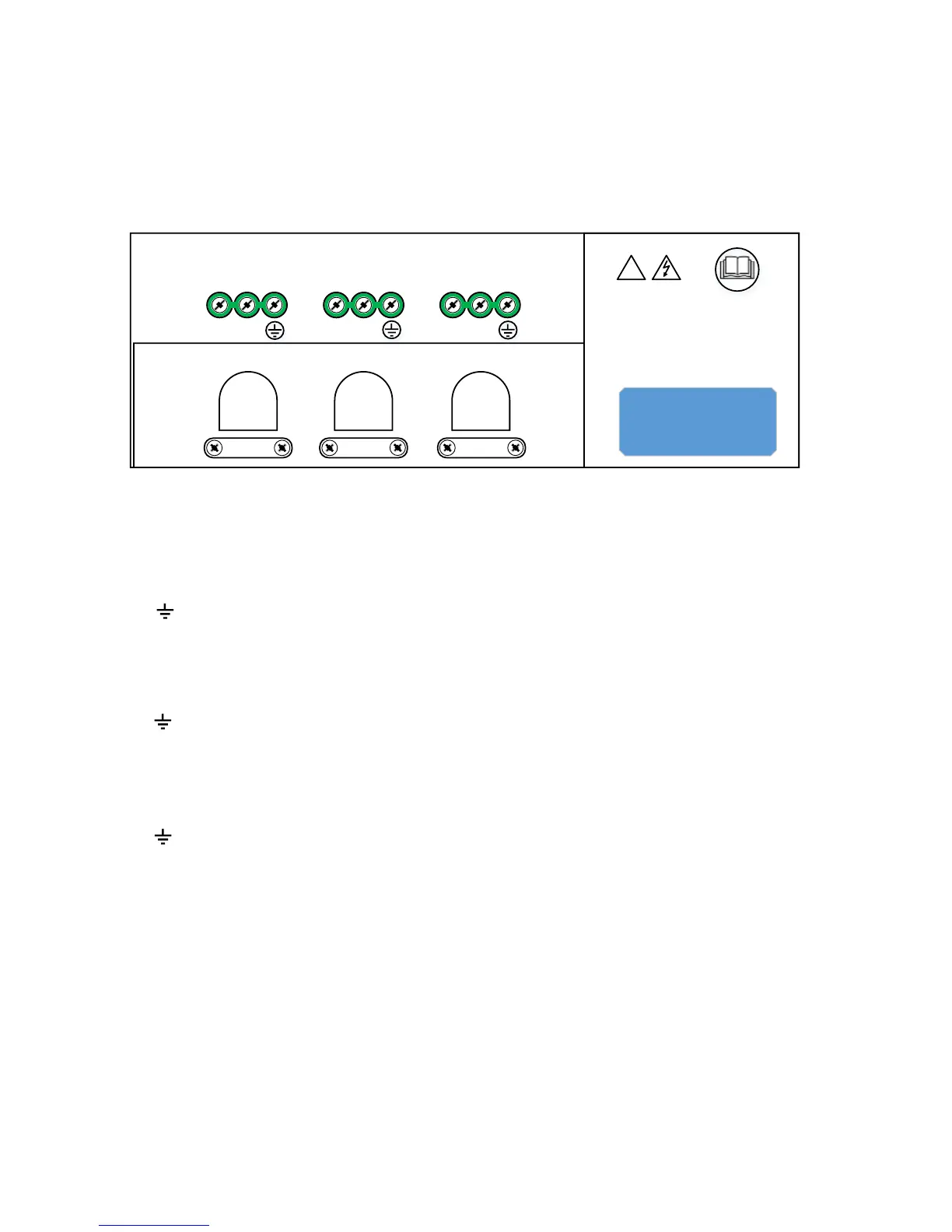
Remove the terminal cover, terminals are arranged as follows:
cut-outs for
rear cable
entry
Terminal Description:
SUPPLY
L 220-240V Live Input—must be protected by 16A MCB or 13A fused outlet
N Neutral
Earth (all earth terminals common)
HTR 1 Terminals (Connect to Immersion Heater at Top of Tank)
+ Connect to the Live terminal of the immersion heater, max 13A
- Connect to the Neutral terminal of the immersion heater
Earth
HTR 2 Terminals (Connect to Lower Immersion Heater, if fitted)
+ Connect to the Live terminal of the immersion heater, max 13A
- Connect to the Neutral terminal of the immersion heater
Earth