INSTALLATION
INSTRUCTIONS
UNPACKING
The carton contains the following:
• Remote control
• Bottom bezel
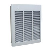
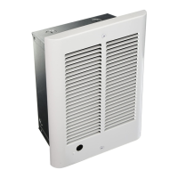
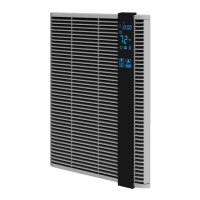
• Grille with installed electronics
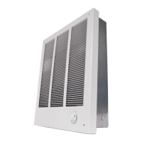
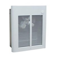
• Heater assembly
• Installation Instructions and User’s Manual
The heater is designed for recessed installation in 2” x 4” (50
mm x 101 mm) stud or larger wall sections using the back box
provided. The heater may be wired with standard building wire
(60°C). Refer to “Specifications” and heater nameplate for
correct supply voltage and wire size.
NOTE: The optimum mounting height for this heater is 18” to 24”
(450 to 600 mm) from floor to bottom of back box. DO NOT
install closer than 12” (305 mm) from the floor.
Preparing Heater For Installation
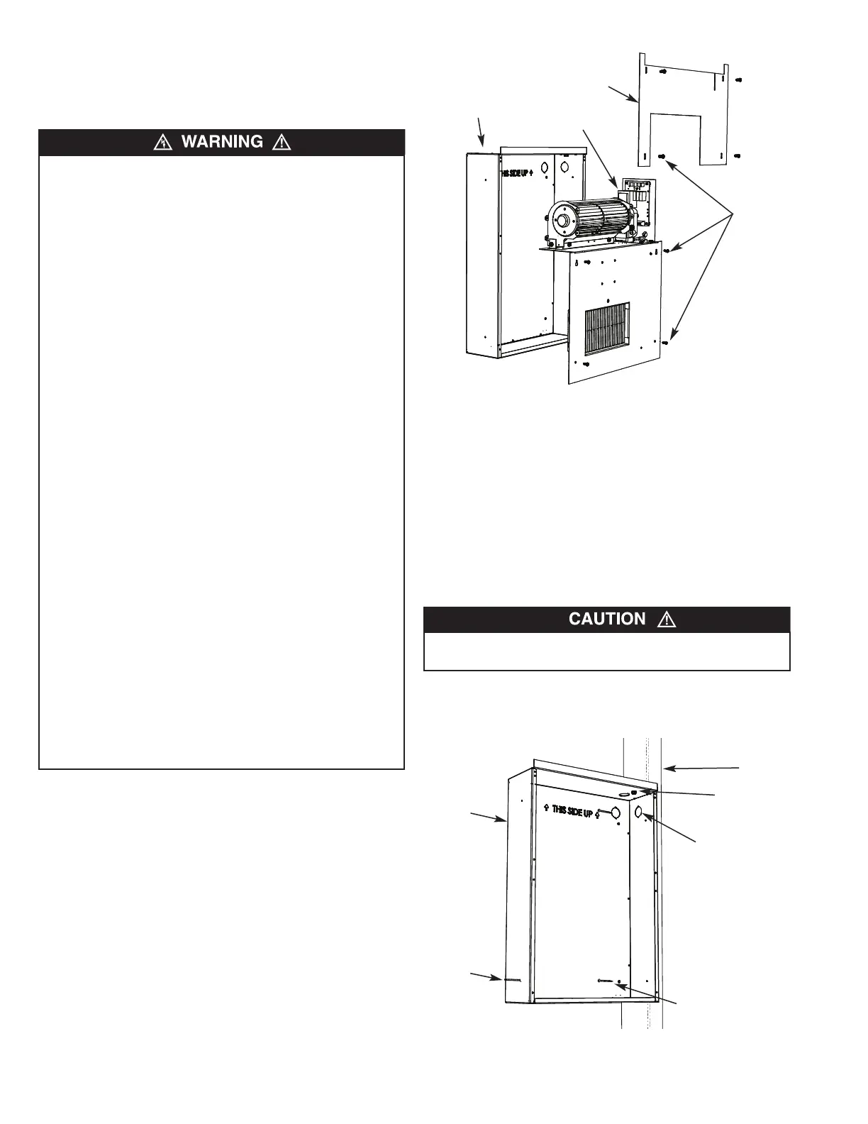
1. Remove the junction box cover / heater assembly from the
back box by removing 8 screws. Set the screws aside since
they will be used to reattach the heater assembly to the back
box later.
NOTE: The junction box cover / heater assembly consists of two
parts. The upper part is referred to as the junction box cover.
The lower part is referred to as the heater assembly. (See Figure
1).
2. Remove one of the knockouts in the side of the back box and
install appropriate cable clamp (not supplied).
Installation of Back Box in New Construction
NOTE: If the finished wall surface is already up, follow instruc-
tions for “Installation of Back Box in Finished Wall”.
To prevent a possible fire, injury to persons or damage to the
heater, adhere to the following:
1. Disconnect all power coming to heater at main service
panel before wiring or servicing.
2. All wiring procedures and connections must be in accor-
dance with the National and Local Codes having jurisdic-
tion and the heater must be grounded.
3. Power supply must enter back box through the knockouts.
See TOP marking on the back box for proper orientation.
4. Verify the power supply voltage coming to heater matches
the ratings as shown on the heater nameplate.
CAUTION: ENERGIZING HEATER AT A VOLTAGE GREATER
THAN THE VOLTAGE PRINTED ON THE NAMEPLATE
WILL DAMAGE THE HEATER AND VOID THE WARRANTY
AND COULD CAUSE A FIRE.
5. CAUTION - High temperature, risk of fire, keep electrical
cords, drapery, furnishings, and other combustibles at least
3 feet (0.9 m) from front of heater. Do not install heater
behind doors, below towel racks, or in an area where it is
subject to being blocked by furniture, curtains or storage
materials. Hot air from the heater may damage certain fab-
rics and plastics.
6. To reduce the risk of fire, do not store or use gasoline or
other flammable vapors and liquids in the vicinity of the
heater.
7. This heater is to be wall mounted only using back box and
may be installed with the back box recessed or surface
mounted. Do not install sideways, upside down, in the ceil-
ing or floor.
8. The following minimum clearances must be maintained:
Bottom of heater to floor - 12 (305 mm).
Sides of heater to adjacent wall - 12” (305 mm).
Top of heater to ceiling - 36” (915 mm).
9. Do not operate the heater without the grille installed.
10. Do not use this heater for dry out as the paint, plaster, saw-
dust and drywall sanding dust will permanently damage the
heater and must be kept out of the heater.
TO PREVENT POSSIBLE DAMAGE TO POWER WIRING,
USE ONLY THE KNOCKOUTS PROVIDED IN BACK BOX.
2
Figure 1- Removing Heater Assembly From Back Box
Knock Out
Hole with
Support Screw
(To Adjacent Stud
Where Possible)
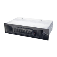
Back
Box
Stud
Ground Screw
Nails or Screws (2)
Figure 2 - Attaching Backbox to Stud
NOTE: The back box must be installed so the front edge
will be flush with the finished surface.
Back Box
Screws
(8) Total
Heater Assembly
Junction Box
Cover