28/52
Mod. 91
5
5. USO DELLA
MACCHINA
5.1 PREDISPOSIZIONI
OPERATIVE PER
TAGLIO CON TESTA
BASCULANTE
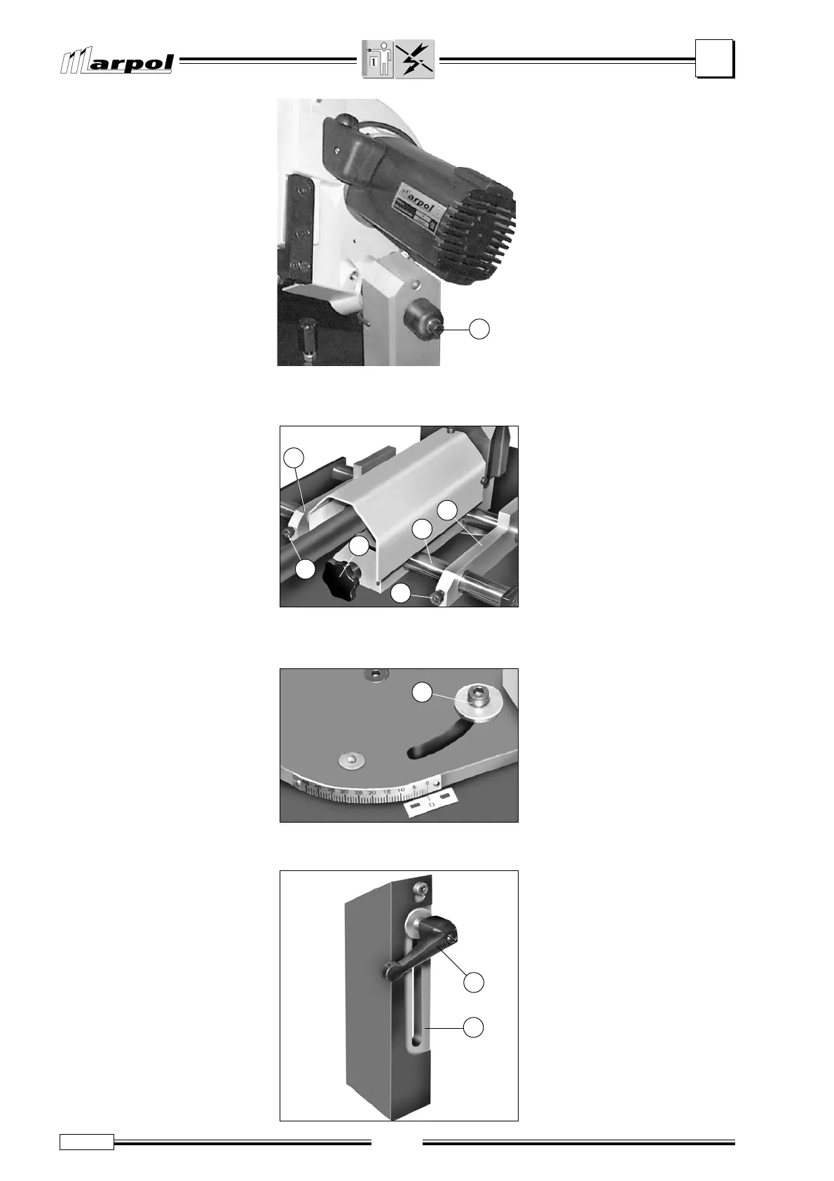
• Sollevare la testa motorizzata a
fine corsa in alto e rilasciarla; non
deve scendere spontaneamen-
te. In caso contrario, serrare con
moderazione la vite (A) che agi-
sce sulla frizione del gruppo di
sollevamento.
• Effettuare alcuni abbassamen-
ti/sollevamenti di prova, dall’im-
pugnatura, la testa deve risultare leggermente “frizio-
nata”. In caso contrario agire nuovamente sulla vite
(A) fino ad ottenere lo scorrimento ottimale.
• Allentare il pomello (B) e far scor-
rere la morsa di bloccaggio pez-
zo, sulle guide cilindriche (C).
• Bloccare la morsa nella posizione
desiderata, tramite il pomello (B).
Nota: la macchina oggetto del pre-
sente manuale, consente infatti di
tagliare pezzi sul lato destro o si-
nistro della morsa.
• Posizionare gli elementi appog-
giapezzo (D) e bloccarli con le
viti (E).
5.1.1 TAGLIO INCLINATO
• Orientare la testa motorizzata, in
funzione del taglio inclinato che
si prevede di praticare, allentan-
do la vite (F) e riferendosi alla
scala graduata.
• Dopo aver selezionata l’inclina-
zione desiderata, bloccare con
forza la vite (F).
F. 4
5.1.2 REGOLAZIONE GUIDA-
LAMA MOBILE
• Allentare la leva (G).
• Far scorrere l’elemento guidala-
ma (H), solidale alla protezione.
5.1.2 ADJUSTING THE
MOBILE BLADE GUIDE
• Loosen the lever (G).
• Slide the blade guide (H) fitted
on the protection
5. OPERATING THE
MACHINE
5.1 PRE-OPERATION
ACTIONS FOR
SWIVEL HEAD
CUTTING
• Lift the motor-driven head at its
top end of stroke and release it;
making sure it does not lowers
spontaneously. If necessary,
tighten the screw (A) to adjusts
the friction force on the lifting
group.
• Try ti lower and lift the head a few
times, acting on the handle: the
head should be slightly “frictioned”. If necessary, act
again on the screw (A) until the head slides
properly.
5.1.1 SLOPE CUTTING
• Position the motor-driven head
according to the slope cutting
to be made acting on the screw
(F) using the graduated scale
as a reference.
• After slecting the required
position, firmly tighten the
screw (F).
• Loose the knob (B) and shift-
ing the piece locking vice along
the cylindric guides (C).
• Lock the vice in the required
position acting on the knob (B).
Note: the machine described in
the present manual has been
designed to cut pieces both on
the right and hand side of the vice.
• Fit the piece supporting devices
(D) and lock them with the
screws (E).
F. 2
D
E
B
D
C
E
H
G
Nota: la leva (G) può in alcuni
modelli, essere sostituita da una
vite.
Note: In some models, the lever
(G) can be replaced by a screw.
F. 1
A
F
F. 3