Do you have a question about the Marshall Amplification MGP 9040 and is the answer not in the manual?
Connects the instrument to the pre-amp unit.
Controls the rhythm gain for both clean (R1) and crunch (R2) selections.
Provides the E.Q. voicing facility on R2.
Controls the level balance between R1 and R2.
Manually selects R2, indicates red when activated.
Manually selects lead mode, indicates red when activated.
Provides the initial gain level of the lead channel.
Provides the secondary gain level of the lead channel.
Provides the E.Q. 'voicing' facility for the lead mode.
Controls the overall level of the lead section.
Tone controls for Bass, Lo-Mid, Mid, High-Mid and Treble.
Push switch for effects on/off.
Controls the level of effects to dry signal.
Controls the overall level of the pre-amp output.
On/off switch for mains power with L.E.D. indicator.
Adjusts the character of the pre-set clean sound.
For connection to the mains power supply.
Provides output to the right hand channel of power amp/mixer.
Provides output to the left hand channel of power amp/mixer.
Selects output level between +4dBm, -10dBv, and -20dBv.
Stereo effects processor output or mono effects return.
Stereo effects processor output for left hand signal.
Rotary level control for matching external effects processor.
Rotary level control for matching pre-amp send to processor input.
Output for linking to input socket of external effects processor.
On/off switch for speaker simulation effect.
Input for connection of line level equipment.
For connection of the external footswitch controller.
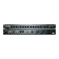
Basic settings for good clean, crunch rhythm and lead overdrive sounds.
Settings for a clean tone, EQ optional.
Settings for crunch rhythm tone, EQ optional.
Settings for a bright lead tone, EQ optional.
Settings for a fat lead tone, EQ optional.
On/off switch for mains power.
Rotary control for the volume level of channel B.
Rotary presence control for channel B.
Standby push switch for channel B.
Standby push switch for channel A.
Rotary presence control for channel A.
Rotary control for the volume level of channel A.
Connection cable to mains power supply.
Refer to label on back for correct fuse value.
HT fuse for channel B only.
Jack input to power amp channel B.
Link to further power amplifiers (channel B only).
Matches output impedance to speaker load.
Twin jack socket speaker outputs for channel B only.
Switches channel B output between 25 or 50 watts.
Switches channel A output between 25 or 50 watts.
Twin jack socket speaker outputs for channel A only.
Matches output impedance to speaker load.
Link to further power amplifiers (channel A only).
Jack input to channel A.
HT fuse for channel A.
On/off switch for mains power.
Rotary control for the volume level of Channel B.
Indicators for fault, fan on, signal, -6dB, clipping.
Indicators for fault, fan on, signal, -6dB, clipping.
Rotary control for the volume level of Channel A.
Connects the amplifier to the mains power supply.
Balanced or unbalanced jack input to power amp channel A.
Balanced or unbalanced XLR input to power amp Channel A.
Twin jack socket speaker outputs for channel A only.
Balanced or unbalanced jack input to power amp channel B.
Balanced or unbalanced XLR input to power amp channel B.
Twin jack socket speaker outputs for channel B only.
Connects the amplifier to the mains power supply.
Refer to the label on the rear for correct fuse value.
Twin jack socket outputs giving 200 watts into not less than 4 ohms.
Jack socket for linking channel A to any further amplifiers.
Input to the power amp channel B only.
Input to the power amp channel A only.
Jack socket for linking channel B to any further amplifiers.
Twin jack socket outputs giving 200 watts into not less than 4 ohms.
Use quality mains plug and wire according to colour code.
Never operate unit without earth; follow wiring practices.
Never bypass fuses or fit incorrect values; do not replace with unit connected.
Do not remove chassis; servicing by qualified personnel only.
Never use in damp/wet conditions; do not obstruct heatsinks.
Do not switch on 9005 without speakers; match impedance selector.
Please read this instruction manual carefully before switching on.
| Brand | Marshall Amplification |
|---|---|
| Model | MGP 9040 |
| Category | Amplifier |
| Language | English |