ENGLISH
12
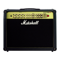
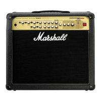
AVT150 & AVT150H Rear Panel Features
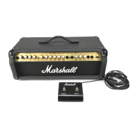
AVT275 Rear Panel Features
FX Loop
As already mentioned, the AVT150 and
AVT150H both boast a Mono Parallel FX loop
for connection with external effects units. In
addition to the FX Mix controls on the front
panel (see ‘Front Panel Features’, point 22) this
FX loop comprises of an FX Send jack, an FX
Return jack and an FX level control button.
6 FX Return
For connection to the output of your
external effects device.
7 FX Level
This should be set to match the level of
the processor being used (generally -10dB for
a stomp box, + 4dB for a professional, rack
unit).
8 FX Send
For connection to the input of the external
device being used.
➲
FX Loop Hints:
a) Always use high quality, shielded patch
cables.
b) If the processor being used has an
input level control, ensure it is set correctly.
c) Time based effects (delays & reverbs)
and modulation effects (chorus, flange, phase,
etc.) are ideal for use in a Parallel FX loop.
d) Certain stomp box effects such as Wah,
distortion, overdrive and fuzz were designed
specifically for use in front of the amp and
sound best when used that way. This said,
tonal beauty is in the ears of the beholder so, if
such a pedal sounds great to you when used in
an FX loop then go for it! Sometimes, there are
no rules...
1 Mains Input Connector
Your AVT is provided with a detachable
mains (power) lead which is connected here.
The specific mains input voltage rating that
your amplifier has been built for is shown on
the back panel. Before connecting for the first
time, please ensure that your electricity supply
is compatible with your amplifier. If you have
any doubt, please seek advice from a qualified
person. Your Marshall dealer will help in this
respect.
2 Loudspeaker Jack Sockets
These connect the internal loudspeakers
to the stereo power amplifier outputs.
WARNING:
Always provide both with a load equal to, or
greater than 8 Ohms.
3 Footswitch
For connection of the supplied stage foot
controller (PEDL-00031). This sturdy 6 way,
Marshall footswitch allows instant selection of
the 4 channels, plus the two DFX modes. It
also features LEDs to indicate status.
4 Headphones
The headphones output is fully emulated
using an improved version of the circuitry found
on the industry standard JMP-1. Turning the
Master Volume (20) to zero will provide silent
practice.
 Loading...