14
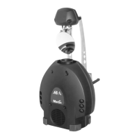
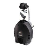
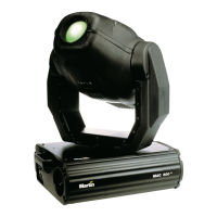
DMX operation
To connect the data link
1 Connect a data cable to the controller’s data output. If the controller has a 5-pin
output, use a 5-pin male to 3-pin female adaptor cable (P/N 11820005).
2Lead the data cable from the controller to the first fixture and plug it into the
data input.
3Connect the output of the fixture closest to the controller to the input of the
next fixture. If connecting to a fixture with reversed-polarity (pin 3 cold), insert
a phase-reversing cable between the two fixtures.
4Continue connecting fixtures output to input. Up to 32 devices may be
connected on a serial link.
5Terminate the link by inserting a male termination plug (P/N 91613017) into the
data output of the last fixture. A termination plug is simply an XLR connector
with a 120 ohm, 0.25 W resistor soldered across pins 2 and 3.
1-CHANNEL DMX OPERATION
The 1-channel DMX mode provides simple remote activation of the MX-4’s stand-
alone programs plus blackout and strobe functions. The 1-channel functions are
shown in Table 5. Each fixture runs its own program and therefore cannot be
synchronized with other fixtures.
DMX value Percent Function
0 - 10
11 - 20
21 - 80
81 - 115
116 - 140
141 - 175
176 - 210
211 - 255
0 - 4
5 - 7
8 - 31
32 - 45
46 - 55
56 - 68
69 - 82
83 - 100
Blackout (light off)
Shutter open (light on)
Strobe
Stand-alone action with slow music trigger
Stand-alone action with medium music trigger
Stand-alone action with fast music trigger
Stand-alone action with random music trigger
Manual trigger area, crossover at 240 (94%)
Table 4: 1-channel DMX functions