Mas Grup
8
9. NOISE LEVEL AND VIBRATION
The reasons which increase the noise level are indicated below:
• Touch of coupling halves due to worn rubber sleeves (incorrectly
aligned)
• Noise level increases due to the fact that the pump is not founded
properly (Vibration)
• If the installation does not have compensator noise and vibration
increases.
• Wearing in ball bearing also increases noise level.
Check if there is any noise increasing elements in your installation.
9.1. Expected Noıse Values
Measurement conditions:
The distance between the measure point
and the pump
Sound Pressure Level (dB) *
Table 2: Sound Pressure Level
(*) Without protective sound hood, measured at a distance of 1 m directly
above the driven pump, in a free space above a sound reflecting surface.
The above values are maximum values. The surface noise pressure level
at dB(A) unit is shown as (L
pA
). This complies withTS EN ISO 20361.
10. DISASSEMBLY, REPAIR AND REASSEMBLY
Before starting work on the pump set, make sure it is disconnected from
the mains and can not be switched on accidentally.
Fallow the safety precautions outlined in “Safety instructions”.
10.1. Disassembly
Close all valves in the suctions and discharge lines. Drain the water in
the pump.
Remove the safety guard.
Because of the pump design, the impeller, shaft and other rotating
parts being removable no need to disconnect the suction and delivery
pipes. If there is not any operation on the casing, not need to remove
the pipe connection.
If to take out the complete pump is necessary, disconnect pump from
the driver, suction and discharge pipes and detach the baseplate (If
Any)
Remove stud nuts (300) which connect the adapter to the casing and
dismantle the rotor group with motor from the volute casing.
Unscrew the end nuts (65) of the impeller and take out the impeller (20)
and impeller key (210). Use rust remover solvent if necessary during
dismantling.
Take out the set screws on the pump shaft and take off the motor by
unscrew the hex bolts (320)
Pull out the rotating part of the mechanical seal (250) from the shaft.
Take out the shaft.
10.2. Reassembly
Reassembly proceeds in reverse sequence to disassembly as
described in section 10.1. You may find the attached drawings useful.
Coat the seats and screw connections with graphite, silicon or similar
slippery substance before reassembly. If you can not find any of the
above you may use oil instead. (Except the pumps for drinking water)
Never use the old o-rings and make sure the o-rings are the same size
as the old ones.
Connect the pump shaft to the motor, fix the setscrews.
Place the stationary part of mechanical seal to its place on the adaptor
(12)
Mount the adaptor to the motor flange.
Slip the rotating part of the mechanical seal onto the pump shaft (61)
Place the impeller key (210) into keyway, slide the impeller (20) onto the
shaft (61) and screw the impeller nuts (65).
Now reassembly of the rotor group is complated.
Finally mount rotor assembly to the volute casing. (In the repair shop
or on site)
Make sure the gaskets and o-rings are evenly placed without sliding
and not damaged or not squezed at all.
Place the pump on the baseplate, couple the motor. Connect suction
and discharge pipes as well as auxiliary pipes. Take the unit into
operation as it was indicated in section 7.
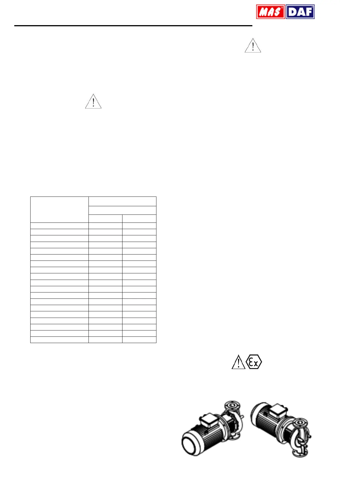
Check whether the faces contacting with another faces are damaged for
avoiding explosion before reassembling of the motor. The parts having
deformed faces must be replaced. Ensure that the rotating parts are fitted
with the guards.
 Loading...