10
IS 2500IS 2500
IS 2500IS 2500
IS 2500
50 Hz50 Hz
50 Hz50 Hz
50 Hz
4.30 Ohm4.30 Ohm
4.30 Ohm4.30 Ohm
4.30 Ohm
60 Hz60 Hz
60 Hz60 Hz
60 Hz
3.80 Ohm3.80 Ohm
3.80 Ohm3.80 Ohm
3.80 Ohm
IS 3500/1IS 3500/1
IS 3500/1IS 3500/1
IS 3500/1
50 Hz50 Hz
50 Hz50 Hz
50 Hz
2.37 Ohm2.37 Ohm
2.37 Ohm2.37 Ohm
2.37 Ohm
60 Hz60 Hz
60 Hz60 Hz
60 Hz
1.86 Ohm1.86 Ohm
1.86 Ohm1.86 Ohm
1.86 Ohm
IS 4500/1IS 4500/1
IS 4500/1IS 4500/1
IS 4500/1
50 Hz50 Hz
50 Hz50 Hz
50 Hz
1.06 Ohm1.06 Ohm
1.06 Ohm1.06 Ohm
1.06 Ohm
IS 5500/1IS 5500/1
IS 5500/1IS 5500/1
IS 5500/1
60 Hz60 Hz
60 Hz60 Hz
60 Hz
0.75 Ohm0.75 Ohm
0.75 Ohm0.75 Ohm
0.75 Ohm
4) SERVICE4) SERVICE
4) SERVICE4) SERVICE
4) SERVICE
All the resistances must be measured when the
alternator is cold, ambient temperature between
10 - 30 °C and with an instrument that allows
reading of given values.
The tolerance against the reported values is
around ± 10%.
Readings taken with simpler instruments can
only indicate the continuity of the winding but
cannot indicate the presence of short circuits.
N.B.
Apart from the possibilities
suggested here-by, one or more
windings could also be grounded
causing a failure.
We suggest therefore to check by
means of a tester that there is no
continuity between the extremities
of the windings and ground.
4.1)Excitation winding4.1)Excitation winding
4.1)Excitation winding4.1)Excitation winding
4.1)Excitation winding
4) CONTROLLI4) CONTROLLI
4) CONTROLLI4) CONTROLLI
4) CONTROLLI
Tutte le misure di resistenza si intendono ese-
guite ad alternatore freddo, temperatura am-
biente 10 - 30 °C e con strumentazione tale da
permettere la lettura dei valori indicati.
La tolleranza rispetto ai valori riportati è indica-
tivamente ± 10%.
letture approssimative, eseguite con strumenti
di portata non adeguata, possono unicamente
indicare la continuità dell'avvolgimento ma non
danno indicazioni su eventuali corto circuiti.
N.B.
Oltre alle possibilità di guasto che
sono indicate in seguito si può
presentare il caso di uno o più
avvolgimenti a massa. Si consiglia
quindi di controllare questa
eventualità verificando con un
tester che non ci sia continuità fra
le estremità dei vari avvolgimenti
(identificati nei paragrafi
successivi) e massa.
4.1)Avvolgimento di eccitazione4.1)Avvolgimento di eccitazione
4.1)Avvolgimento di eccitazione4.1)Avvolgimento di eccitazione
4.1)Avvolgimento di eccitazione
Caratteristiche - Characteristics:Caratteristiche - Characteristics:
Caratteristiche - Characteristics:Caratteristiche - Characteristics:
Caratteristiche - Characteristics:
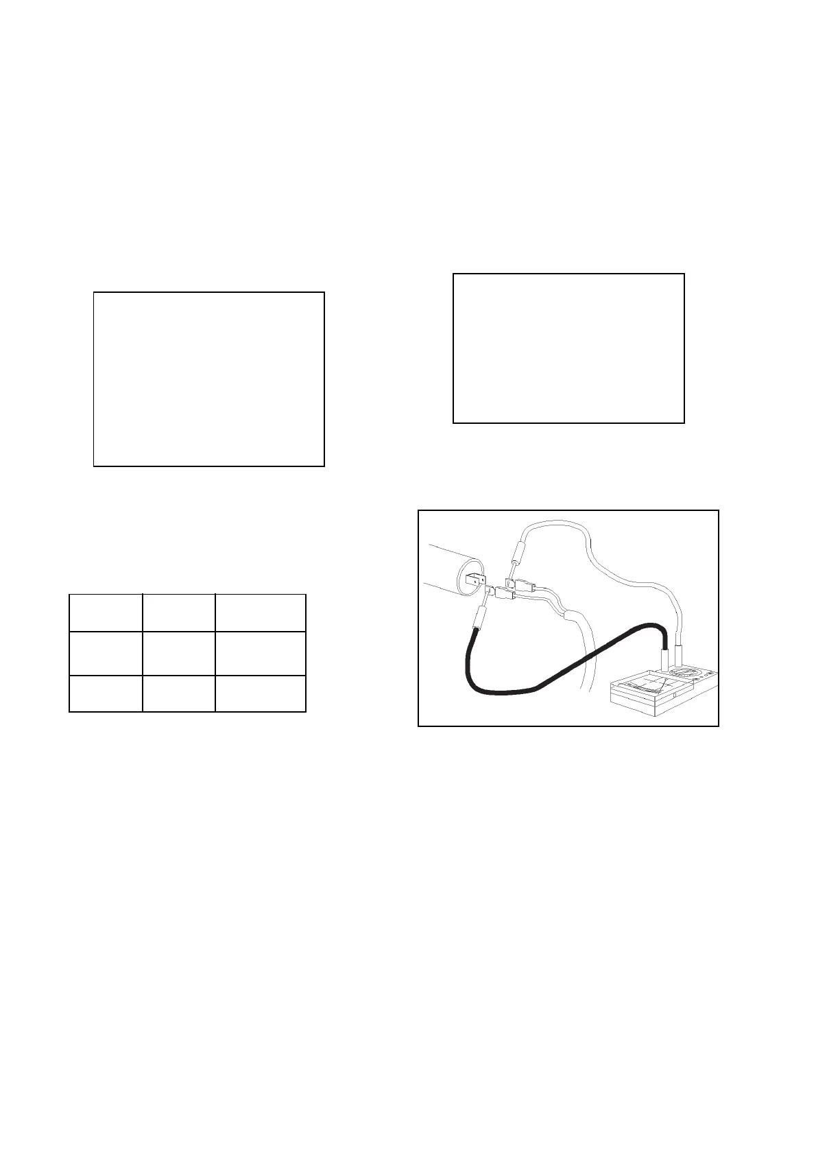
Fig. 3Fig. 3
Fig. 3Fig. 3
Fig. 3
Testing method:Testing method:
Testing method:Testing method:
Testing method:
-Disconnect from the capacitor the two wires
(color: BLUE) coming from the stator (Fig. 3).
-Verify that the resistance values between these
two wire terminals are within the limits as
reported in the table above.
REMEDY: REMEDY:
REMEDY: REMEDY:
REMEDY: Replace the stator.
Metodo di controlloMetodo di controllo
Metodo di controlloMetodo di controllo
Metodo di controllo
- Scollegare dal condensatore i due cavi (BLU)
provenienti dallo statore (Fig. 3).
- Verificare che la resistenza fra le estremità dei
due cavi rientri nei valori indicati in tabella.
RIMEDIO: RIMEDIO:
RIMEDIO: RIMEDIO:
RIMEDIO: Sostituire lo statore.