11
4.2) Power winding4.2) Power winding
4.2) Power winding4.2) Power winding
4.2) Power winding
4.3)Avvolgimento di carica batteria4.3)Avvolgimento di carica batteria
4.3)Avvolgimento di carica batteria4.3)Avvolgimento di carica batteria
4.3)Avvolgimento di carica batteria
Caratteristiche - Characteristic:Caratteristiche - Characteristic:
Caratteristiche - Characteristic:Caratteristiche - Characteristic:
Caratteristiche - Characteristic:
4.3)Battery charger winding (stator)4.3)Battery charger winding (stator)
4.3)Battery charger winding (stator)4.3)Battery charger winding (stator)
4.3)Battery charger winding (stator)
Metodo di controllo:Metodo di controllo:
Metodo di controllo:Metodo di controllo:
Metodo di controllo:
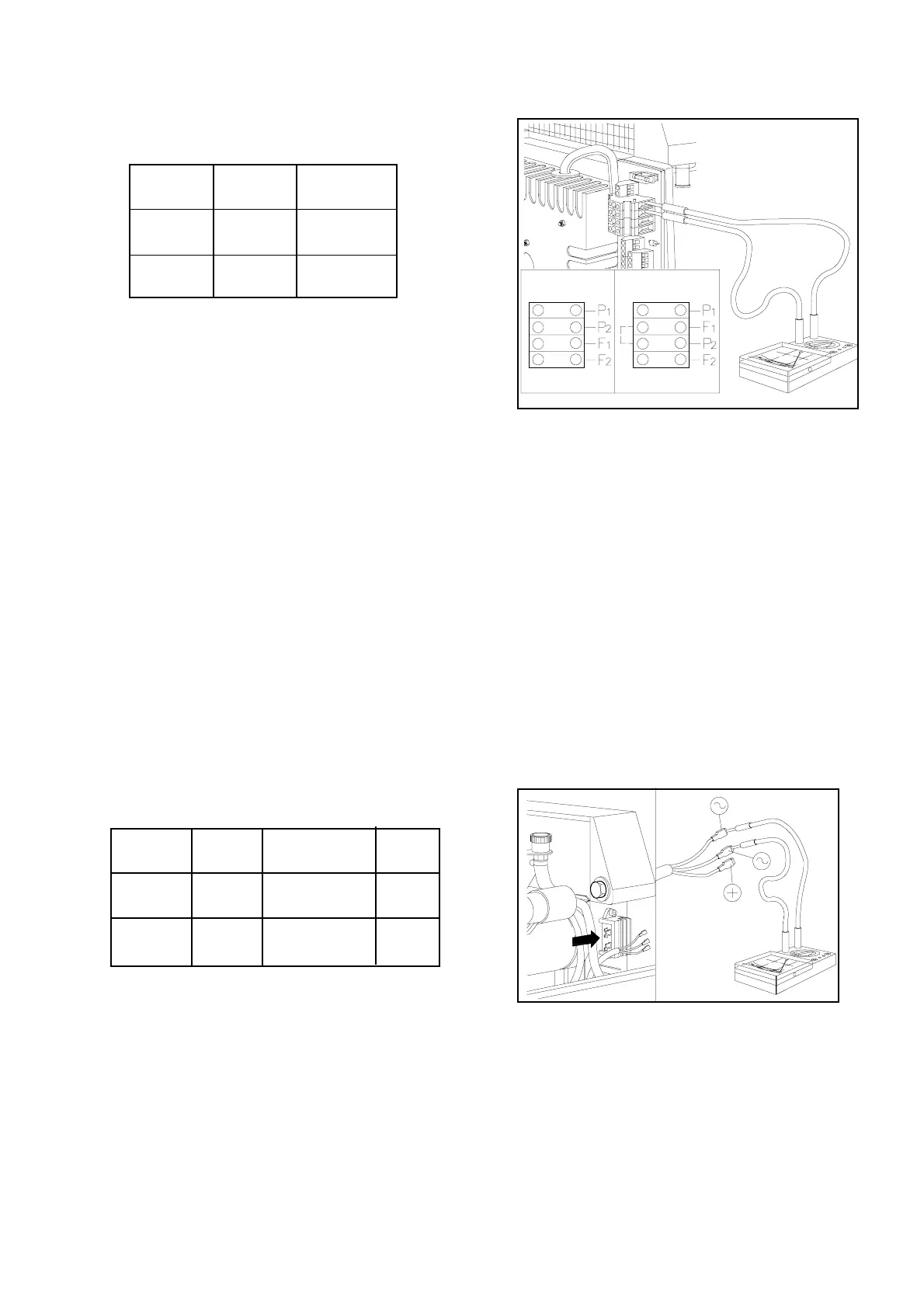
-Scollegare dalla morsettiera i cavi di potenza
contrassegnati dalle lettere P
1
F
1
P
2
F
2
(Fig. 4).
-Verificare che la resistenza fra le estremità di
entrambe le coppie di cavi P
1
F
1
e P
2
F
2
rientri nei
valori indicati in tabella.
N.B.N.B.
N.B.N.B.
N.B. La resistenza totale dell'avvolgimento (nel
collegamento 220 V o 240 V) si misura
ponticellando F
1
e P
2
. La misura effettuata fra i
punti P
1
e F
2
sarà il doppio del valore indicato in
tabella.
RIMEDIO: RIMEDIO:
RIMEDIO: RIMEDIO:
RIMEDIO: Sostituire lo statore
Testing method:Testing method:
Testing method:Testing method:
Testing method:
- Disconnect from the terminal board, the wires
coming from the stator, marked by the letters P
1
F
1
P
2
F
2
(Fig. 4).
- Verify that the resistance values between the
two pairs of wire terminals P
1
F
1
and P
2
F
2
are
within the limits as reported in the table above.
N.B.N.B.
N.B.N.B.
N.B. The total resistance value for power wind-
ing (220 V 240 V) is measured connecting F
1
and P
2
. the resistance value measured between
P
1
and F
2
is double of that indicated in the table
above.
REMEDY: REMEDY:
REMEDY: REMEDY:
REMEDY: Replace the stator.
Fig. 4Fig. 4
Fig. 4Fig. 4
Fig. 4
IS 2500IS 2500
IS 2500IS 2500
IS 2500
50 Hz50 Hz
50 Hz50 Hz
50 Hz
0.15 Ohm 13 V0.15 Ohm 13 V
0.15 Ohm 13 V0.15 Ohm 13 V
0.15 Ohm 13 V
60 Hz60 Hz
60 Hz60 Hz
60 Hz
0.10 Ohm0.10 Ohm
0.10 Ohm0.10 Ohm
0.10 Ohm
13 V 13 V
13 V 13 V
13 V
IS 3500/1IS 3500/1
IS 3500/1IS 3500/1
IS 3500/1
50 Hz50 Hz
50 Hz50 Hz
50 Hz
0.18 Ohm0.18 Ohm
0.18 Ohm0.18 Ohm
0.18 Ohm
13 V 13 V
13 V 13 V
13 V
60 Hz60 Hz
60 Hz60 Hz
60 Hz
0.10 Ohm0.10 Ohm
0.10 Ohm0.10 Ohm
0.10 Ohm
13 V 13 V
13 V 13 V
13 V
IS 4500/1IS 4500/1
IS 4500/1IS 4500/1
IS 4500/1
50 Hz50 Hz
50 Hz50 Hz
50 Hz
0.10 Ohm0.10 Ohm
0.10 Ohm0.10 Ohm
0.10 Ohm
13 V 13 V
13 V 13 V
13 V
IS 5500/1IS 5500/1
IS 5500/1IS 5500/1
IS 5500/1
60 Hz60 Hz
60 Hz60 Hz
60 Hz
0.10 Ohm0.10 Ohm
0.10 Ohm0.10 Ohm
0.10 Ohm
13 V 13 V
13 V 13 V
13 V
Fig. 5Fig. 5
Fig. 5Fig. 5
Fig. 5
Testing method:Testing method:
Testing method:Testing method:
Testing method:
Disconnect the wires coming from the regulator
(Fig. 5) and verify that the resistance values
between the green wires are within the limits
indicated in the table above.
AS AN ALTERNATIVE:
-Verify that the voltage between the GREEN
wires is as reported above.
Metodo di controllo:Metodo di controllo:
Metodo di controllo:Metodo di controllo:
Metodo di controllo:
-Scollegare i cavi dal regolatore (Fig. 5) e
verificare che la resistenza fra i cavi verdi rientri
nei valori indicati in tabella.
IN ALTERNATIVA:
-Verificare che fra i cavi verdi la tensione alter-
nata rientri nei valori indicati in tabella.
IS 2500IS 2500
IS 2500IS 2500
IS 2500
50 Hz50 Hz
50 Hz50 Hz
50 Hz
1.00 Ohm1.00 Ohm
1.00 Ohm1.00 Ohm
1.00 Ohm
60 Hz60 Hz
60 Hz60 Hz
60 Hz
0.90 Ohm0.90 Ohm
0.90 Ohm0.90 Ohm
0.90 Ohm
IS 3500/1IS 3500/1
IS 3500/1IS 3500/1
IS 3500/1
50 Hz50 Hz
50 Hz50 Hz
50 Hz
0.52 Ohm0.52 Ohm
0.52 Ohm0.52 Ohm
0.52 Ohm
60 Hz60 Hz
60 Hz60 Hz
60 Hz
0.44 Ohm0.44 Ohm
0.44 Ohm0.44 Ohm
0.44 Ohm
IS 4500/1IS 4500/1
IS 4500/1IS 4500/1
IS 4500/1
50 Hz50 Hz
50 Hz50 Hz
50 Hz
0.20 Ohm0.20 Ohm
0.20 Ohm0.20 Ohm
0.20 Ohm
IS 5500/1IS 5500/1
IS 5500/1IS 5500/1
IS 5500/1
60 Hz60 Hz
60 Hz60 Hz
60 Hz
0.18 Ohm0.18 Ohm
0.18 Ohm0.18 Ohm
0.18 Ohm
4.2)Avvolgimento di potenza4.2)Avvolgimento di potenza
4.2)Avvolgimento di potenza4.2)Avvolgimento di potenza
4.2)Avvolgimento di potenza
Caratteristiche - Characteristic:Caratteristiche - Characteristic:
Caratteristiche - Characteristic:Caratteristiche - Characteristic:
Caratteristiche - Characteristic: