5
583152 - Masport Lawnmower Owner’s Manual - March ‘17 PANTONE 648C
grass, leaves, or excessive grease.
6. Check the catcher bag frequently for deterio-
ration and wear, and replace worn bags. Check
that replacement bags comply with the original
manufacturer’s recommendations or specifica-
tions.
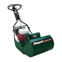
STORING THE MOWER
The handle can be folded to minimise space
requirements.
FOLDING THE HANDLE. Loosen the clamp
knobs or unlock the handle lever(s) in the middle
of the handle and fold the top section over the
engine.
Ergoshift models can also be stored by moving
the handle to the upright position.
CAUTION
Check that the control cables are not being
strained while folding and unfolding the
handle. Permanent kinks will make the
controls difficult to operate.
TIPPING THE MOWER SAFELY FOR STOR-
AGE OR INSPECTION.
Tilting the mower—Drain fuel, then tilt the
mower with the spark plug uppermost.
Remove the spark plug lead.
CAUTION
ASSEMBLING THE
MOWER
Please refer to the following sections when
preparing the mower for its first use.
• Fitting the handle
• Preparing the Engine
• Assembling the catcher
NOTE - The left and right sides of the mower are
referred to as viewed from the operating position
behind the handle.
FITTING THE HANDLE
In some cases the handle may be completely
detached from the mower body although the
upper handle may be connected by the throttle
control cable. Carefully remove the mower and
handles from the box together to avoid damag-
ing the throttle control.
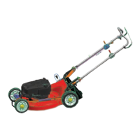
Assembling the ‘Screw Lock’ Handle.
The lower handle is fitted to the mower using
the four bolts located in the handle brackets,
two on each side, ‘A’ in the drawing below. To
bolt the lower handle to the mower fit the bolts
through the lower handle then fit the handle
to the mower body and tighten the nuts on the
outside of the mounting brackets using a 13mm
A/F socket or spanner.
Now attach the upper handle to the lower
handle.
420MM MODELS
The 420mm model is shipped with the handle
completely detached from the mower body
although the upper handle may be connected by
the throttle control cable to the engine. Carefully
remove the mower and handles from the box
together to avoid damaging the throttle control
and cable.
Assembling the Lower Handle
The lower handle stubs are fitted to the
mower using the four bolts located in the handle
brackets, two on each side, ‘B’ in the drawing
below. To bolt the lower handle to the mower fit
the bolts through the lower handle then fit the
handle to the mower body and tighten the nuts
on the inside of the housing using a 13mm A/F
socket or spanner.
Now attach the upper handle to the lower
handle stubs.
Take care not to rotate the handle before fitting
it, as this will tangle the control cable(s).
CAUTION
Fit the two long bolts through the holes in the
lower handle from the inside with the round
heads snug against the tube. Fit the holes in the
upper handle over the two long bolts. Make sure
that the throttle control is located on the right
hand side. Attach the plastic knob to the outside
of the lower handle bolt as shown below and
tighten by hand until the upper handle is locked
in position.
Assembling the ‘Cam Lock’ Handle.
Most of these models are fully assembled when
packed, so all that is needed is to remove them
from the carton, swing the handle to the operat-
ing position and lock the handle lever(s).
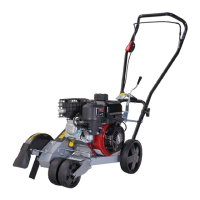
The camlock handles on some mowers are
reversed for shipping. To turn them around
unwind the nut to the end of the thread with
a 13mmA/F spanner/socket, pull the camlock
handle outwards and rotate it 180
o
. Retighten
the nut until the handle locks firmly in place and
it does not change position when in use.
The correct locked
position after refitting.
Locked position
when Shipped.
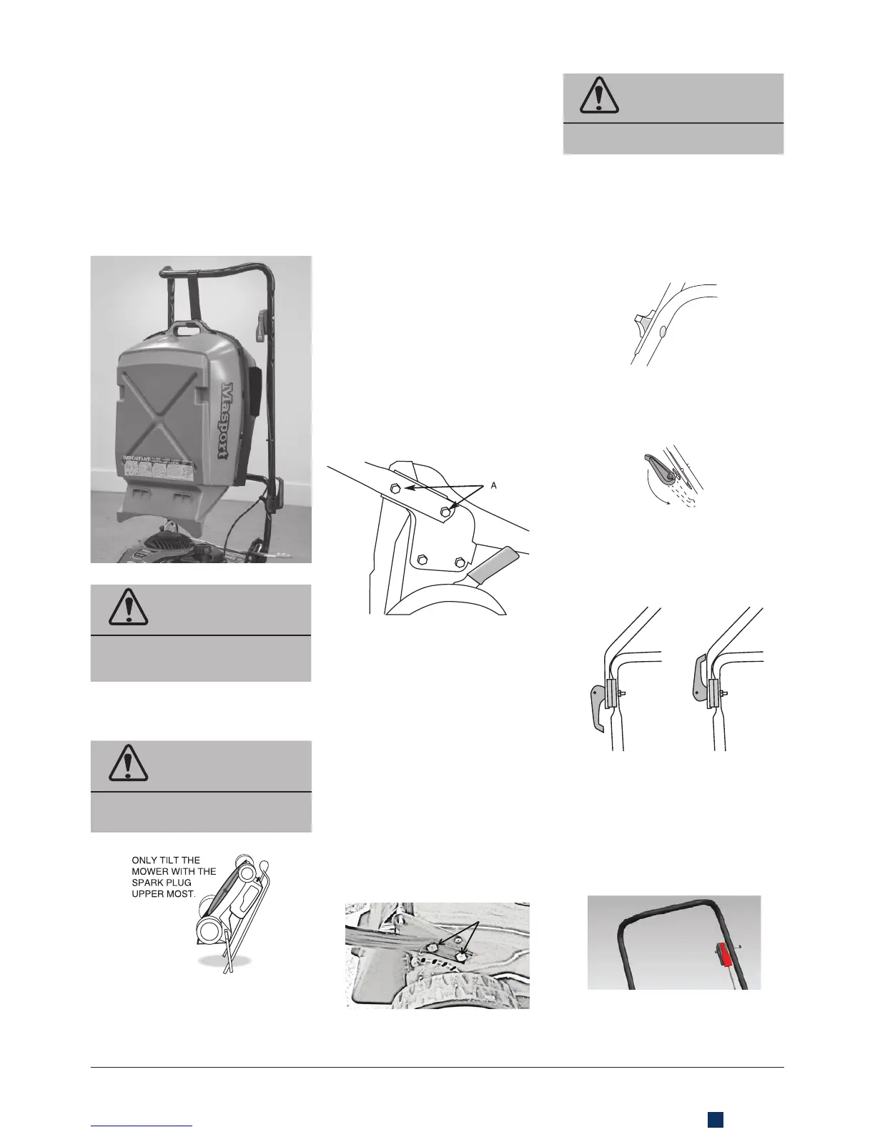
FITTING THE THROTTLE CONTROL
In some cases the throttle control may be
completely detached from the upper handle.
Using the bolt and nut attached to the throttle
control, attach the throttle on LH side of the
upper handle (inside the handle).
 Loading...