TESTED NEW ZEALAND FLUES:- In New Zealand we recommend the use of genuine Masport flue kits
or kits approved by Masport. The flue MUST be installed in accordance with the detailed instructions
accompanying it. Grandview & Toronto ceiling plates must be at least 450mm square. A flue heat
shield (including a top dispersal cap), as detailed on page 4, must be fitted at the back of the flue
(directly above the stove) to achieve the reduced wall clearances shown in the table. The Masport flue
heat shield kit for 150mm flues is Part No 551481, while the kit for 178mm flues is Part No 551793.
Kits include mounting brackets and heat dispersal caps.
OTHER FLUE SYSTEMS
Flues and flue heat shields other than those listed above may be used, but if they have not been tested
with these heaters, their installation clearances will be those specified in AS/NZS 2918:2001 for
untested flue installations. Unless otherwise specified on page 4, all heat sensitive wall material must
be kept at least 600mm away from any flue which is not fitted with a flue heat shield.
FIXING THE WOODFIRE IN POSITION
Once the flue shielding system has been installed through the ceiling and roof, the woodfire can be
placed in its approximate position on the floor protector, and the flue pipes installed. Finally adjust the
stove position making sure the flue is vertical and that the necessary minimum woodfire-to-wall
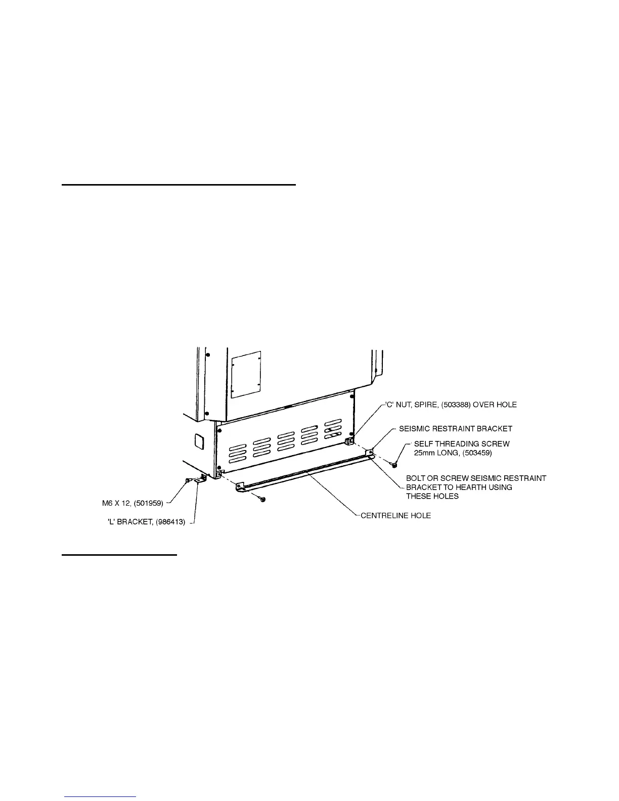
distances are being achieved. In New Zealand and some parts of Australia, Standards require that the
woodfire and floor protector be secured to prevent shifting in the event of an earthquake. This is best
done by fastening the woodfire right through the protector to the floor, using two screws not less
than 12 gauge, or the equivalent size of coach bolts or toggle fasteners. Anchor the appliance through
the holes in the seismic restraint bracket at the rear of the pedestal or in the two angle brackets
supplied. The angle brackets attach at each side of the pedestal (except for some of the smaller
models, where they attach at the rear). The pedestal can be fastened to the seismic restraint bracket
either before or after fitting the anchor screws. The small centreline hole in the bracket will help in
pre-positioning it.
FINAL ASSEMBLY
Before using the woodfire, confirm that the internal firebox components are in their correct positions.
(See ‘FIREBOX LINERS” in the Maintenance section).
Reach down through the flue spigot and carefully remove the polystyrene packing above the firebox
top baffle, remembering that the baffle can be broken by rough handling. Make sure that the baffle is
correctly placed on top of the supporting shelves at each side of the firebox, and that it is back far
enough for the two front corners to drop behind the retaining ribs on top of the shelves. On some
models, a metal reinforcing channel is provided for the baffle. Fit this along the edge of the baffle
nearest the door.
If you need to remove the top baffle, first withdraw the secondary air tube following the instructions
in the Maintenance section.
In cases where a pedestal foot is to be fitted, simply fit the trim into the foot and slide the assembly
onto the pedestal, keeping the foot in contact with the Floor protector all the time to avoid marking
the finish on the sides of the pedestal.
Finally, spread the sand provided evenly over the bottom of the firebox and refit the door, if
necessary, before lighting the first fire.
8
 Loading...