EasyManua.ls Logo

Masseuse Ultimate Chiro - Distribution and Functions of the Power Board & Main Board Pluggable Unit

Masseuse Ultimate Chiro
31 pages
Print Icon
To Next Page IconTo Next Page
To Previous Page IconTo Previous Page
Loading...
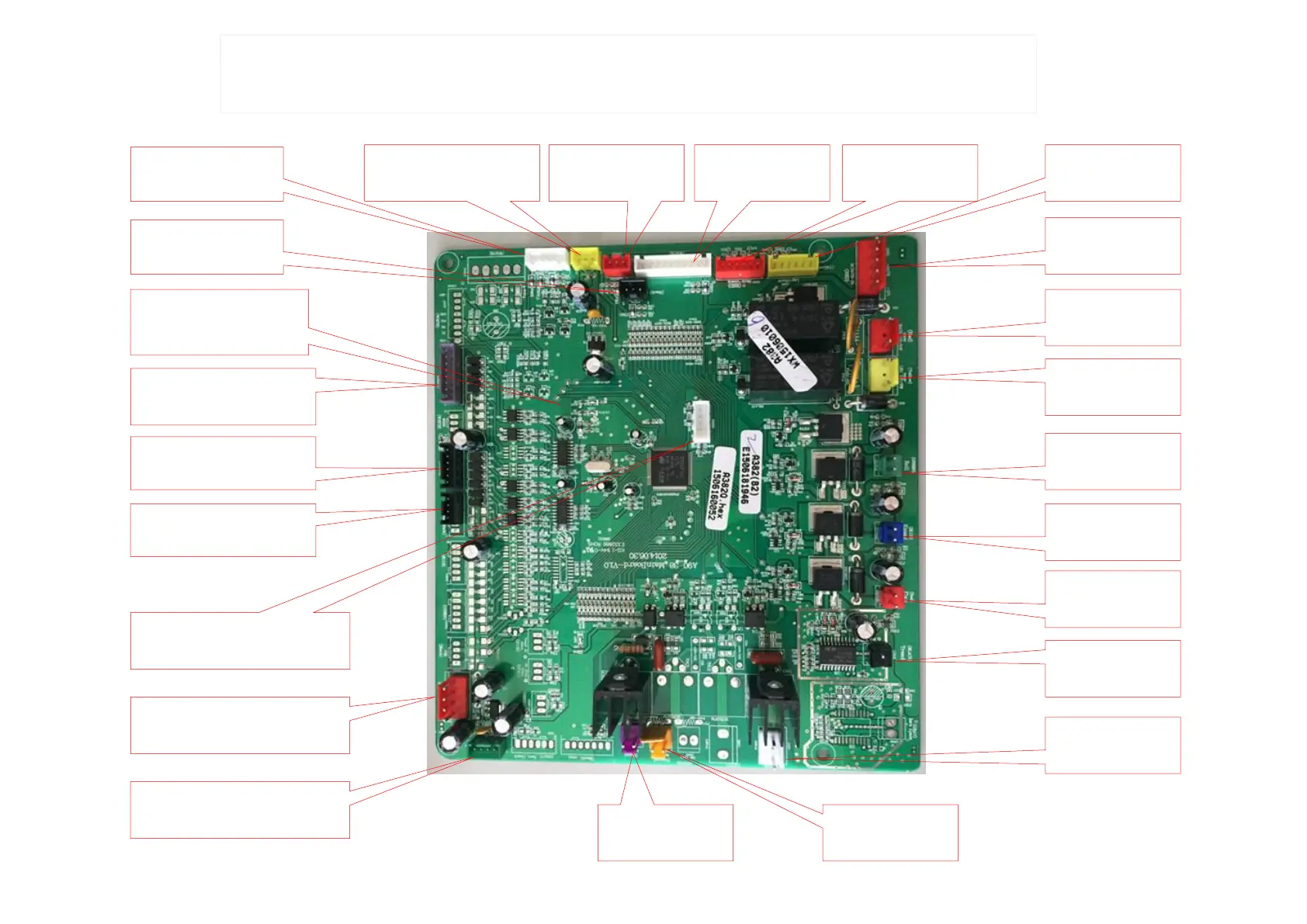
III. Distribution and functions of the Power board & Main board pluggable unit
(Figure 5)
CON47:
controller wire
CON46:+5VA &
start signal
CON22: Top limits switch of
massage mechanism
CON42: Bottom limits switch of
massage mechanism
CON45:Massage
mechanism function
testing wire
CON3:Testing wire of
backrest actuator
CON2: Testing wire
of calf rest actuator
CON44:24VB/12V
flat cable
CON39:power supply
of back rest actuator
CON37: power supply
of calf rest actuator
CON31 green:Foot
rolling motor
CON48 blue :
kneading motor
CON25 red:
flapping motor
CON19 black :
traveling motor
CON7: Air
pump
CON5: Transfer AC22V
to back heating
CON6:Input AC22V
to main PCB board
CON10:Protection switch of
power supply box
CON21:24VA/+5VB
CON33:Solenoid valve of
armrest
CON38:Solenoid
valve of calf rest
CON34 : USB program
connector
DC 3.3V Power indicator
MCU operation indicator
CON29:Solenoid valve of
armrest