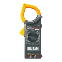
1. TRANSFORMER JAWS
2. BARRIER OR TACTILE
INDICATOR
3. DATA HOLD SWITCH
4. TEMPERATURE
MEASURING SOCKET
5. ROTARY SWITCH
6. LCD DISPLAY
7. DROP-PROOF WRIST
STRAP
8. INPUT JACKS
9. TRIGGER
FUNCTION AND RANGE SELECTOR
A rotary switch is used to measurement functions and ranges.
When the switch is set to OFF position, the meter does not operate.
TRANSFORMER JAWS
Pick up the AC current flowing through the conductor. Press the
TRIGGER to open the transformer jaws. When the finger press on
the TRIGGER is released, the jaws will close again.
DATA HOLD
Depress HOLD Button Switch to toggle in and out of the Data Hold
mode. Releasing Data Hold mode again press the button.
INPUT JACKS
This meter has three input jacks that are protected against overload
to the limits shown.
During use connect the black test lead to COM jack and connect
red test lead to V jack. The red test lead is depended on function
selected.
The EXT jack is used for accept insulation tester unit EXT banana
- 3 -
Plugs, when measurement insulation resistance.
3. OPERATING INSTRUCTION
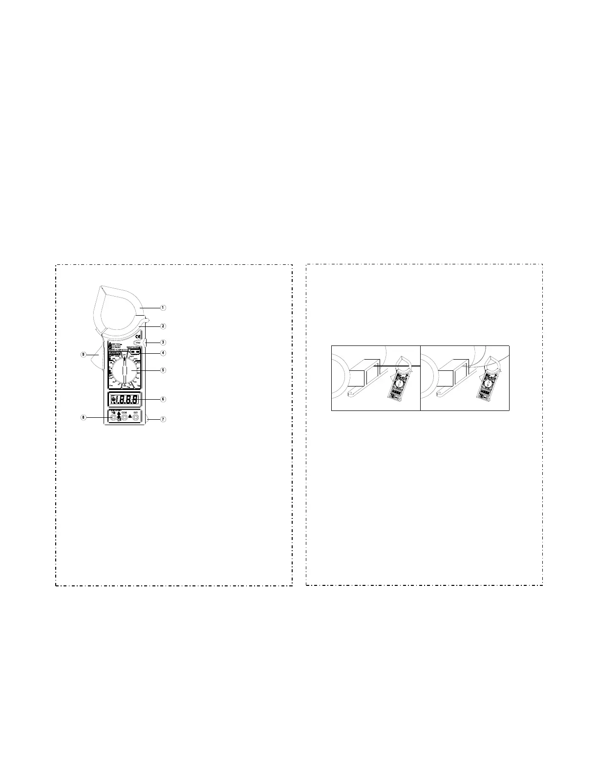
MEASURING CURRENT
1. Set the rotary switch at desired A~ range position. Press the
trigger to open the transformer jaws and clamp onto one conductor
only (Fig1), The transformer jaws pick up the AC current flowing
through the conductor.
2. When only the figure“1”displayed, it indicates overrange
situation and the higher range have to be selected.
WRONG CORRECT
Fig1
INSULATION TEST
(Option 500V insulation tester unit)
1. Connect the insulation tester unit V 、COM、EXT three-
banana plugs to the clamp meter V、COM、EXT.
2. Set the rotary switch of clamp meter at 2000M position.
3. Set the insulation tester unit range switch to the 2000M
position.
4. Uses the insulation tester unit of the test leads connects its L、
E input connect to being tested installations. (Test installation's
must be power OFF)
5. Set the insulation tester power switch to the ON position.
6. Depress the PUSH 500V push-push switch; the 500V on red
LED lamp will light. Clamp meter display reading is the insulation
resistance value. If the reading is below 19M, change clamp
meter and insulation tester unit to 20M range, can be increasing
the accuracy.
7. If the insulation tester unit is not use, the power switch must
shift to power OFF position, and the test leads must leave the E. L
input connect. That can be increase battery life and prevent
electrical shock hazard.
- 4 -
 Loading...