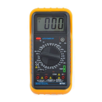
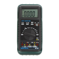
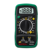
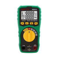
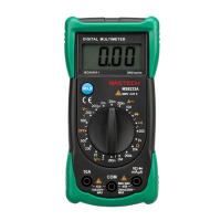
MEASURING VOLTAGE
1. Connect the black test lead to the COM jack and the red test
lead to the V jack.
2. Set the rotary switch at the desired V or V~ range position
and connect test leads across the source or load under
measurement. The polarity of the red lead connection will be
indicated along with the voltage value when making DC voltage
measurement.
3. When only the figure“ 1 ”is displayed, it indicates overrange
situation and the higher range has to be selected.
MEASURING RESISTANCE
1. Connect the black test lead to the COM jack and the red test
lead to the V jack.
2. Set the rotary switch at desired position and connect test
leads across the resistor under measurement.
NOTE:
1. If the resistance being measured exceeds the maximum value of
the range selected or the input is not connected, an overrange
indication“ 1 ”will be displayed.
2. When checking in - circuit resistance, be sure the circuit under
test has all power removed and that all capacitors have been
discharged fully.
TESTING DIODE
1. Connect the black test lead to the COM jack and the red test
lead to the V jack. (The polarity of red lead is“ + ”)
2. Set the rotary switch at position and connect red lead to
the anode, black lead to the cathode of the diode under testing.
The meter will show the approx. forward voltage of the diode. If the
lead connection is reversed, only figure“ 1 ”displayed.
CONTINUITY TEST
1. Connect the black test lead to the COM jack and the red test
lead to the V jack. (The polarity of the red lead is positive
“ + ”)
2. Set the rotary switch at position and connect test leads
across two points of the circuit under testing. If continuity exists
(i.e., resistance less than about 100), built -in buzzer will sound.
MEASURING TEMPERATURE
1. Set the rotary switch at ℃ or ℉ position and the LCD display
will show the current environment temperature.
2. Insert“ K ”type thermocouple into the temperature measuring
socket on the front panel and contact the object to be measured
with the thermocouple probe. Read LCD display.
- 5 -
WARNING:
To avoid electric shock, be sure the thermocouple has been
removed before changing to another function measurement.
MEASURING FREQUENCY
1. Connect the black test lead to the COM jack and the red test
lead to the V jack.
2. Set the rotary switch at Hz position and connect test leads
across the source or load under measurement.
NOTE:
1. Reading is possible at input voltage above 10V rms., but the
accuracy is not guaranteed.
2. In noisy environment, it is preferable to use shield cable for
measuring small signal.
4. SPECIFICATIONS
Accuracy is specified for a period of one year after calibration and at 18℃
to 28℃ ( 64℉ to 82℉) with relative humidity to 80%.
4.1 GENERAL
: 3 1/2 digit LCD, with automatic polarity
indication
Terminals and earth ground
: 1000V dc or 750V rms ac (sine)
: Dual-slope integration A-D converter
: ”1” Figure only in the display
: ”―”displayed for negative polarity
: 0℃ to 40℃ (32℉ to 104℉)
: -10℃ to 50℃(14℉ to 122℉)
: 9V alkaline or carbon-zinc battery
( 6F22 or equivalent )
: Operating manual ,set of test leads
: ” BAT ” to left of display
: Thermocouple ( K type )
: 96(W)235(D)46(H) mm
: 330g ( including battery )
- 6 -
 Loading...