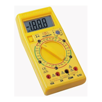
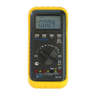
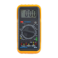
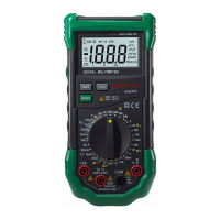
06
3.4 Testing diode
2.When checking in-circuit resistance, be sure the circuit under
test has all power removed and that all capacitors have been
discharged fully.
3.For measuring resistance above 1MΩ, the meter may take a
few seconds to get stable reading. this is normal for high
resistance measurements.
1.Connect the black test lead to the COM jack and the
red test lead to the V/Ω jack. (The polarity of red lead
is “+ ”).
2.Set the rotary switch at position and connect red
lead to the anode, black lead to the cathode of the
diode under testing. The meter will show the approx.
Forward voltage of the diode. If the lead connection
is reversed, only figure“1”displayed.
3.5 Testing transistor
1.Set the rotary switch at hFE position.
2.Determine whether the transistor to be tested is NPN
or PNP type and locate the Emitter,Base and
Collector leads. Insert leads of the transistor into
proper holes of the transistor testing socket.
3.The meter will show the approx. hFE value at test
condition of base current 10µA and Vce 2.8V .
3.6 Continuity test
1.Connect the black test lead to the COM jack and the
red test lead to the V/Ω jack.( The polarity of the red
lead is positive“+”).
2.Set the rotary switch at position and connect test
leads across two points of the circuit under testing. If
continuity exists ( i.e., resistance less than about 30Ω ),
built-in buzzer will sound.