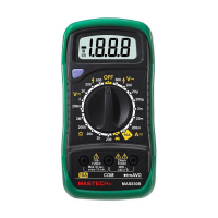
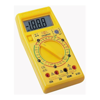
Set the rotary switch at “hFE” position.
Determine whether the transistor under testing is NPN
or PNP and locate the emitter,base and collector leads.
Insert the leads into proper holes of the hFE socket on
the front panel.
Read the approximate hFE value at the test condition of
base current 10A and Vce 3V.
NOTE:
To avoid electrical shock, remove test leads from
measurement circuits before testing a transistor.
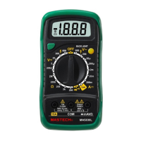
Circuit On-Off measurement
Insert the black probe to the “COM” jack the red one
into the “V..mA” jack.
Turn the switch to the position and connect the
probes in parallel with two points is less than 100, the
built-in buzzer will beep to indicate the continuity
between the two points.
Turn the switch to the ℃ position and insert the black
probe of the thermocouple sensor into COM jack the red
one into the V..mA jack. Place the operating terminal
(temperature measured and directly read the
temperature value in ℃ on the display.
When the switch is turned to the ℃ position and the
sensor is in an open circuit, the display shows room
temperature.
Replacement of battery and fuse
1. Under normal conditions, it is unnecessary to replace the
fuse. Don’t replace it until the probes are unplugged and
the power is shut down. Take out the two screws of the
rear cover to remove the housing.
2. The specification of the fuse is:
F1 250mA/250V, F2 10A/250V.
10